When you click on links to various merchants on this site and make a purchase, this can result in this site earning a commission. Affiliate programs and affiliations include, but are not limited to, the eBay Partner Network.
Odd variation on the inaccurate temperature sender theme
I've encountered a odd issue with an aftermarket temperature sender (a NAPA TS6469, in particular). All the data I've gathered points to a case of "thermal run away" within the sending unit.
By that I mean that once the sending unit begins to warm and its resistance starts to decrease, the extra current which passes through the sender warms it more, which causes the resistance to decrease more, which causes more current to flow...... and so on, until my temperature gauge pegs. From start to finish, this process takes about 5 seconds after the gauge needle begins to move.
If you are curious (or bored) read on while I explain what I've observed.
Of course, I've verified that the engine isn't actually overheating:
1. Thermostat is still closed, upper hose is cool.
2. Thermocouple measurement indicates a temperature of about 140 F.
3. IR gun finds nothing unduly hot.
Before I installed the TS6469, I characterized its resistance vs. temperature curve as follows:
Temp Resistance
160 155
175 129
190 109
203 88
(I live at an elevation of almost 4000'. 203 was the maximum temperature achievable with boiling water.)
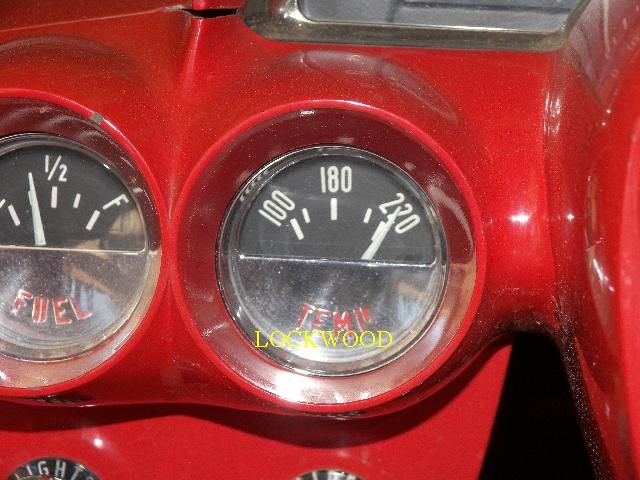
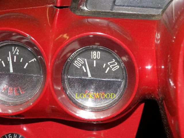
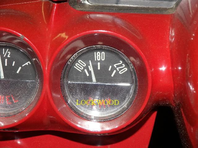
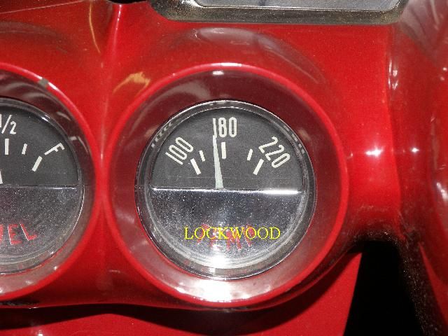
I also characterized my car's temperature gauge to see how it might respond to this aftermarket sending unit. Using available fixed resistors to simulate the resistance of the sending unit I got surprisingly good results:
Fixed resistor of 147 Ohms (approximating 160F):
Fixed resistor of 128 Ohms (approximating 175F):
Fixed resistor of 104 Ohms (approximating 190F):
Fixed resistor of 81 Ohms (approximating something greater than 203F):
These are all good results and they indicated the sending unit was an acceptable match to my car's gauge. They were also stable results. For example, the resistance of the sending unit never dropped below 88 Ohms when left in boiling water and the gauge reading never varied, no matter how long I left the fixed resistors in place.
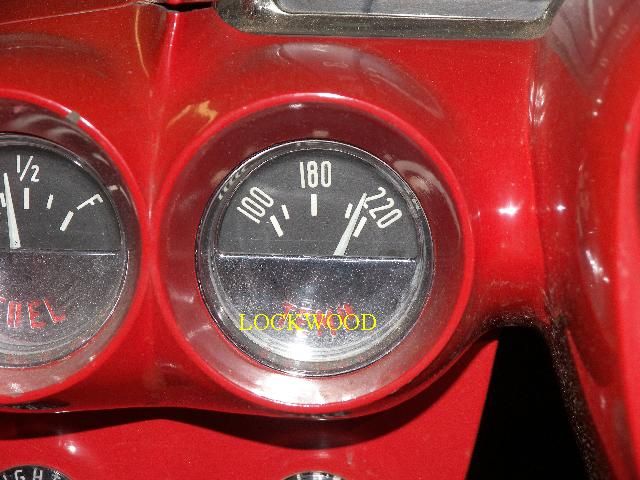
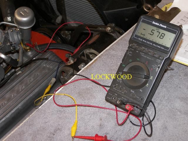
So what happened when I ran my car's engine with the TS6469 sending unit connected (other than the gauge pegging)?
For one thing, the current through the sender shot up to well over half an amp:
Let's think about that for a moment.
Engine was running when that picture was made, so let's say system Voltage was about 14 Volts. Ohm's law says that the resistance of the gauge + resistance of the sender is 14 Volts divided by current of .58 Amps, or about 24 Ohms.
That's significantly less than the known resistance of just the sender when immersed in 203F water! And, keep in mind that the actual engine temperature was only about 140F!
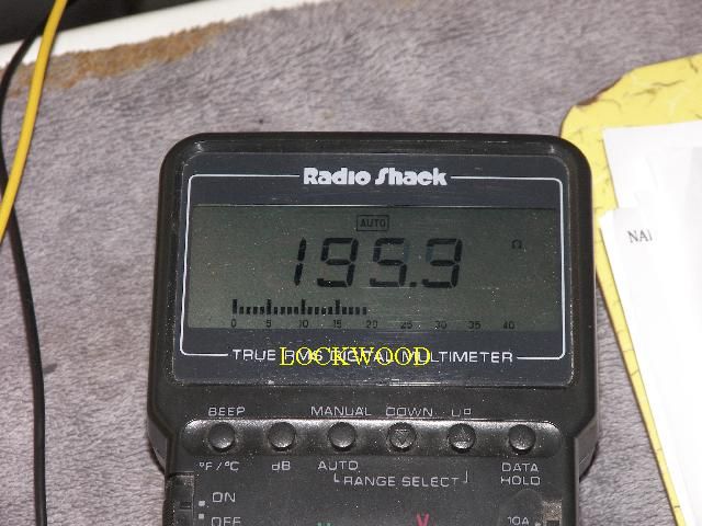
It's also different from the resistance I measured when I quickly reconfigured my DVM connections after shutting the engine off (which killed current through the sender):
195 Ohms suggests a temperature a little warmer than 145, consistent with the readings I get from the permanently attached thermocouple.
The only explanation I can imagine is that the sending unit was self-heating as more and more current passed through it..... i.e. thermal run away.
But why?
Is there insufficient coolant for the sending unit to be completely immersed? Seems unlikely. The coolant recovery tank (this is a top tank '60) has plenty of coolant in it and the engine has been through several warm-up/cool-down cycles.
Is the thermistor inside the sending unit electrically connected to the case but thermally isolated from it? I've never heard of this happening and I don't know anything about the inner construction of the sender. Is it even possible?
Frankly, I'm puzzled. I'm convinced there is something really abnormal about the sending unit and I'll probably try another one just to see if this is a fluke.
Till then, I'm eager to get anyone's theories, ideas, or to read about any experience even remotely similar.
It does occur to me that, to some extent, all temp sending units could be susceptible to thermal run away since they are negative temperature coefficient devices. I wonder if some of the false indications of overheating which are so commonly reported might be due to similar but less dramatic cases of thermal run away. Hmmmmmm......
That part is called a temperature sender SWITCH unit on eBay. I'm thinking its not correct for your application. Maybe for an idiot light?
That's a fair question and it would initially appear that even NAPA is confused. Look up TS6469 on the NAPA web site and you get this page: ts6469 for both gauge and light
But look at either listing and it becomes clear that the sender is actually for a gauge..... in spite of NAPA's confusion.
Thanks. Can't help it.... I'm an engineer. It's what I do.
Can I assume that the battery voltage was 14.2 with the engine running? I.e., the VR is in good working condition?
Charging system works correctly and 14.0 - 14.2 Volts would be a good assumption. But if system Voltage had been, say, 12 Volts instead, the resistance which produced .58 Amps would have been less than I calculated. That would represent an even worse condition.
So, regardless of system Voltage (or coolant temperature) the sending unit is just making it all up.
Sounds like a design problem or a manufacturing defect. The sensing element should have enough thermal contact with the probe end of the sensor housing so that any electrically generated heat is transferred to the water in the cooling system.
I never cut one of these things open to see what's inside, but I'm guessing the sensing element is attached to the probe end with a thermally conductive, electrically insulating solid material or is immersed in thermally conductive, electrically insulating liquid like oil.
Sounds like a design problem or a manufacturing defect. The sensing element should have enough thermal contact with the probe end of the sensor housing so that any electrically generated heat is transferred to the water in the cooling system.
I agree completely. I'm leaning towards a manufacturing defect being the explanation.
When (no longer "if") I replace this sender with another TS6469, I expect to prove this to my satisfaction.
You have done a logical and thorough testing, the problem is these sending units. First, there are 2 different sending units that look identical but one is for a light, and the other is for a gage. Make sure you are starting with the correct one.
Next, the internal thermistors are easily effected and can degrade over time as well. I had one that worked perfectly for years but when I swapped intakes and put that one back in the new manifold it appeared to be working properly at idle but would shoot up 20* as the RPM's increased then go right back down when at idle . Started to think I had a "real problem" but the IR gun solved confirmed I did not. Apparently, it did not like the new manifold or maybe the resistance was somehow changed during the R&R. These things are crimped together in the final assembly phase of production. I have read that the nature of this very manufacturing process itself can cause variances in readings between the senders.
Pilot Dan
Also check post #12 in this thread where that # sending unit was found to also read high:
When you go back to the store, have them cross reference a Wells TU-5 to their own brand and see what they come up with. That unit supposedly gives fairly accurate readings.
You have done a logical and thorough testing, the problem is these sending units. First, there are 2 different sending units that look identical but one is for a light, and the other is for a gage. Make sure you are starting with the correct one.
Dan, the distinction between senders for lights and those for gauges is decidedly important. NAPA lists two similarly numbered senders:
TS6469 for a gauge (which is what I have)
and
TS6469SB for a light (which is what the poster in the thread you recommended has..... no wonder his gauge reads high.... internal switch closes and gauge pegs!)
Next, the internal thermistors are easily effected and can degrade over time as well.
Do you know what degrades? Does the resistance curve change?(Resistors tend to drift up in value as they age, though, not down.) Does the internal thermal bond between the case and the thermistor degrade?
I have read that the nature of this very manufacturing process itself can cause variances in readings between the senders.
I certainly believe that, especially since these are not sold as precision measurement devices.
Originally Posted by rongold
When you go back to the store, have them cross reference a Wells TU-5 to their own brand and see what they come up with. That unit supposedly gives fairly accurate readings.
Weeeellllll, it's like this: When I ordered the sender by phone, I asked specifically for a TU5. "Got one in stock", the chipper but youngish store manager replied. My bride was headed into town anyway so she picked it up, not suspecting what she bought wasn't what I had specified.
I realized immediately it wasn't a TU5, of course, but I was curious enough to test it. Go back to the characterization curve for this sender. It's actually fine. In fact, if anything, were it not for the self heating that happens when significant current flows through it, the TS6469 would cause the gauge in my car to actually read low.
From studying other posted resistance/temperature curves for TU5 senders, my gauge would read less accurately (meaning too low) with one than it should with the NAPA sender.
Going forward, I intend to get my hands on another TS6469, test it in hot water, and then try it on my car's engine.
If it self heats and pegs the gauge, they both go back and I'll declare the problem a genetic defect with NAPA senders.
If it produces a stable reading which tracks actual engine temperature, I'll chalk up the problem with the first sender to a manufacturing defect and declare victory.
I had a very similar experience with a water temp sender for a Stewart Warner WT gauge I have in my 56,,, I ordered the right sender from Summit, (got the part number from SW tech)...
Long story short, I tested teh sender in a pot of water I heated, and used a known good mechanical gauge to monitor teh temp,,, I went thru 2-3 senders, before one read teh right temp...
I chalk it up to QC, and lack of testing on just about anything now a days... I guess its cheaper to replace faulty parts then to test them at teh manufacturing level,,, unfortunately for us..
Jim I can only guess that since this item is a crimped electrical assembly it may be suseptible to changes due to condensation.
With regards to your temp readings though, your photo shows your guage reading about 135* using 147 ohms. I'd expect to see closer to 180*.
I just checked the ohms on the one in my car (new Paragon calibrated sender) and I get 156 ohms with the I/R gun confirming just under 180* actual engine temp.
How about running a dedicated separate wire directly to the back of your Temp gauge (where the blue wire attaches) and put an external known resistance source separate from the cars system to it and see what it reads. That would be the equivalent of bench testing it without the bother of removing the guage from the car. I'd be interested to see what you come up with
Any current new fixes to this issue? I am having the same issues and no solutions thus far! 4 different brand senders in and no luck changing the issue. Gauge till shoots up to 220 after 5 min of running.. Car on the heat gun is 180..
As part of my investigation, I sacrificed an original Delco sender and a current production NAPA/Echlin sender to study their insides. In the modern sender, the thermistor element element is about 1/3 the size of the element in the Delco sender and it does not make good thermal contact with the brass case.
I don't know that other senders currently being manufactured are constructed like the Echlin sender, but since the thermal runaway problem is widespread, I suspect many are. In any event those two factors make it a losing game to try to find a modern Echlin sender which doesn't experience thermal runaway.
The most simple solution is to obtain and install an original Delco sender. Extremely well made, they work properly.
I took a different approach for no better reason than I could.
I designed two circuits: First circuit powers the sender at a very low level and absolutely, positively prevents the sender from going into thermal runaway. The second circuit drives the gauge. Connecting these two circuits is a tiny computer which "reads" the sender output, does some arithmetic, and then outputs a signal to gauge circuit.
With this contraption, I can use any modern sender, get accurate results, and not have to put up with thermal runaway.
Admittedly, there some complexity associated with what I did. It's not for everyone.
That said, for anyone who knows how to use a soldering iron and can download the program code to the small computer, I'll gladly share schematics, parts list, and program source code.
 08-29-2013, 09:32 PM


 . Started to think I had a "real problem" but the IR gun solved confirmed I did not. Apparently, it did not like the new manifold or maybe the resistance was somehow changed during the R&R. These things are crimped together in the final assembly phase of production. I have read that the nature of this very manufacturing process itself can cause variances in readings between the senders.
  Pilot Dan


 Car on the heat gun is 180..