'64 Keeps Getting Stuck in 1st Gear
 07-09-2009, 04:48 PM
#21
Le Mans Master

Member Since: Nov 2000
Location: Going too fast over the hill. Iowa
Posts: 7,246
Likes: 0
Received 18 Likes
on
16 Posts

If you shim the tail of the trans up to clear the crossmember, use an angle finder to verify that both ujoints have the same deflection angle and are between 1� and 3�. Otherwise you will probably have a vibration.
 07-13-2009, 12:15 PM
#22
Pro

Thread Starter

How are the transmission levers keyed or splined ? From what I see on the outside there is only a washer and a nut, but no 'notch'.
Since my transmission is in neutral when the levers are 'back', how do I get the levers to go vertical like in the picture above once I get a new shifter and linkage ?
My thought would be to loosen the lever connection hardware and face the levers at the 90 degree vertical position. I'm just not clear on how they rotate the rods...
07-13-2009, 04:19 PM
#23
Burning Brakes

How are the transmission levers keyed or splined ? From what I see on the outside there is only a washer and a nut, but no 'notch'.
Since my transmission is in neutral when the levers are 'back', how do I get the levers to go vertical like in the picture above once I get a new shifter and linkage ?
My thought would be to loosen the lever connection hardware and face the levers at the 90 degree vertical position. I'm just not clear on how they rotate the rods...
Since my transmission is in neutral when the levers are 'back', how do I get the levers to go vertical like in the picture above once I get a new shifter and linkage ?
My thought would be to loosen the lever connection hardware and face the levers at the 90 degree vertical position. I'm just not clear on how they rotate the rods...
 07-13-2009, 04:23 PM
#24
Pro
Thread Starter
So, how does a new shifter and linkage arms affect the trans lever orientation / clock position ???
How do I get the levers to point straight up and down if the transmission is in neutral while the levers are 'back' ? Loosen the lever bolts ? Then position vertically ? How does the notch you describe locate to the levers if the levers are notched and in neutral when 'back' ?
What am I missing (besides a brain) ?
07-13-2009, 05:41 PM
#25
Safety Car

Member Since: Nov 2004
Location: going faster miles an hour...with the radio on in browns mills new jersey
Posts: 4,154
Likes: 0
Received 71 Likes
on
45 Posts

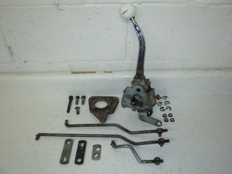
The levers have slots in them. The angle that the slot is machined at determines the orientation. If the levers are put on "inside out", they can end up way out of wack. The picture below shows the correct parts for your application. Note that the slots in the 1-2 and 3-4 levers are pretty much straight up and down. How do yours compare?
07-13-2009, 11:22 PM
#26
Pro
Thread Starter
The levers have slots in them. The angle that the slot is machined at determines the orientation. If the levers are put on "inside out", they can end up way out of wack. The picture below shows the correct parts for your application. Note that the slots in the 1-2 and 3-4 levers are pretty much straight up and down. How do yours compare?
Not sure what mine look like, need to strip them off maybe this weekend and disassemble.
DS
Thanks for the picture of all the components.
07-14-2009, 08:02 AM
#27
Burning Brakes
So, that statement would lead me to believe that the rods they are on have flats machined into them on either side... is that correct ?
Not sure what mine look like, need to strip them off maybe this weekend and disassemble.
DS
Thanks for the picture of all the components.
Not sure what mine look like, need to strip them off maybe this weekend and disassemble.
DS
Thanks for the picture of all the components.
A muncie in neutral will position the arms straight up, not back on a seevere angle.

Click on the .pdf link for "the" install instructions for the 64 with a muncie.
http://www.jegs.com/InstallationInst...0-373-3162.pdf
Last edited by muncieman; 07-14-2009 at 08:18 AM.
07-14-2009, 11:17 AM
#28
Pro
Thread Starter
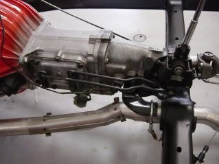
So the transmission shift shafts are the two shown in the red oval below ?
And those are the ones that have the flats machined into them (so that the flats of the lever slots mate flush to them, providing the surface to 'turn' the shaft when the lever is actuated by the rod) ?

So what I need to determine is how the slots are machined into part #8 and #12 and what clock position the two shift shafts are in (what orientation the flats are when the transmission is in neutral) ?
DS
And those are the ones that have the flats machined into them (so that the flats of the lever slots mate flush to them, providing the surface to 'turn' the shaft when the lever is actuated by the rod) ?
So what I need to determine is how the slots are machined into part #8 and #12 and what clock position the two shift shafts are in (what orientation the flats are when the transmission is in neutral) ?
DS
Last edited by DesertSpider; 07-14-2009 at 11:24 AM.
07-14-2009, 11:25 AM
#29
Pro
Thread Starter
What happens if I find out that the transmission shaft slots are NOT vertical when the transmission is in neutral ?
Does that mean that I need to pull the transmission and open the case to reset the shaft orientations ?
DS
Does that mean that I need to pull the transmission and open the case to reset the shaft orientations ?
DS
Last edited by DesertSpider; 07-14-2009 at 08:54 PM.
08-01-2009, 11:59 AM
#30
Pro
Thread Starter
UPDATE:
So........ had an EXTREMELY unfortunate event happen last night. As this nightmare unfolded, I instantly recalled reading about this very thing somewhere here in the forums (but can not find the exact thread).
Long story short, got the old shifter and linkage removed from the transmission. Got the appropriate Hurst for my application (with the proper reverse shift lever), got the corresponding linkage kit and installed all of that (alignment / adjustment, etc.) in roughly an hour.
BIG BIG BIG MISTAKE. When attaching the linkage levers to the transmission shift shaft, I put the plate(s) on in their necessary vertical position, [side note update: all shift shafts were vertical (from earlier discussion questions), I'll post pics later], ran the washer, lock washer and nut all down snug by hand. Then put a socket on the nut(s) and proceeded to tighten firmly.
ABSOLUTE BRAIN FART MELTDOWN As the nut tightened down the reverse lever started to give (front/back position) a little which gave me the impression that the nut was not completely tight. Once last / final turn of the driver and SNAP !!!!!
I SNAPPED THE REVERSE TRANSMISSION SHIFT SHAFT CLEAN OFF.....
HOLY **** !
As thermonuclear lava flowed through my veins for the next 45 minutes straight I felt like someone shot me in the gut with a 10 ga. automatic shotgun about 100 times.......
Now what ? Luckily the way the shaft broke there is still 1 to 2 threads left if you take the washer and the lock washer out of the equation. Meaning that the set-up now looks like: trans side case, shift shaft, reverse lever, then nut (but there's definitely not enough thread engagement that makes me feel comfortable a) that it's tight b) it won't vibrate loose / work loose once shifted a dozen times or so and c) won't end up causing more problems (like the lever completely falling out), getting stuck in reverse somewhere away from home, etc. etc. etc.
I could have sworn that I read a post here that described this exact sequence and SPECIFICALLY said: "DO NOT tighten with a driver, use a wrench". Can't seem to find the post though, if it is here somewhere, please point me to it (possibly some good advice how to fix w/o pulling the transmission). Also, if that post is not here the mods should put this advice in the C1 / C2 FAQ section ref: Shifter / Transmission Linkage Assembly CRITICAL process warnings.
So, what I want to know is: what now ? My buddy that was helping last night said that there are a couple of options.
His thought was to weld the nut cavity that is exposed to the rough end of the trans shift shaft (then when I'm ready to do a full transmission rebuild, I can pull it all out of there and do an end-to-end fix / upgrade). That way at least for now I can keep the transmission and shifter functioning properly while I'm working through other problems / projects.
The second idea is to get rid of the nut and weld the lever directly to the shift shaft, again, necessitating a deeper teardown / rebuild at some time in the future.
Who else has been in this situation and what did you do ?
I know the scenario of pulling the transmission and shifter out of the vehicle.
Are there any suggested temp. fixes w/o pulling the transmission ???
HELP
DS
Last edited by DesertSpider; 08-02-2009 at 10:43 PM.
 08-17-2009, 11:00 AM
#32
Drifting

I don't know how hard the reverse shaft would be to come by but....
I had my 4 speed rebuilt by a local speed shop that builds tranny's for drag and stock cars. I needed and input shaft with gears, synchros,3rd gear and new bearings. My shop let me know that parts are getting hard to come by because these old muncies are the preferred tranny for stock cars and are being bought up as fast as they go on the market.
I don't know if there is enough material on the reverse shaft but could you drill it in about 1/2 inch deep and tap it out to accept a bolt?