Complete rebuild of 53-62 front cross member and suspension
 05-31-2009, 03:27 PM
#1
Race Director


Thread Starter
Member Since: Mar 2001
Location: Mustang OK
Posts: 13,852
Received 3,773 Likes
on
1,674 Posts
2023 C1 of the Year Finalist - Modified
2015 C1 of the Year Finalist

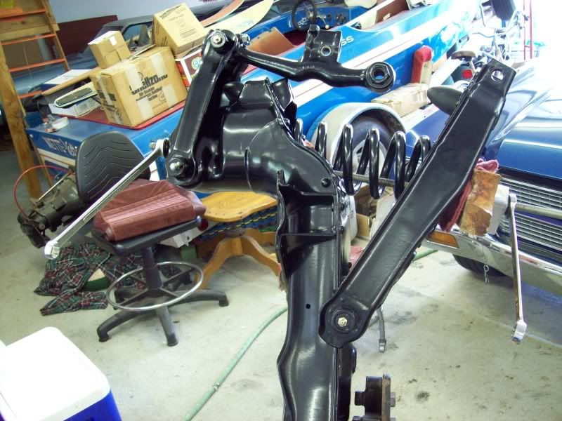
This is going to take a long time to put together--------------maybe all night.
But here is where we start
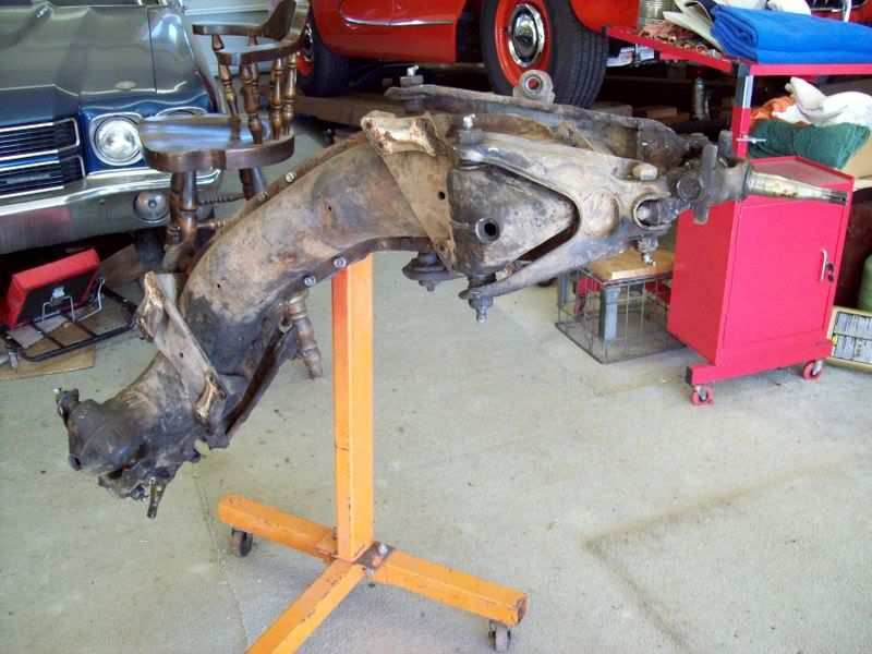
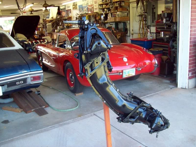
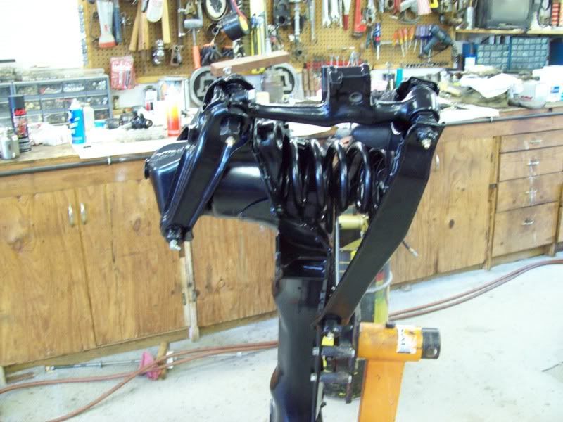
And here is where we finish.
The frontend rebuild in the following pictures is from a 57 Corvette which appeared to have never been rebuilt. Also, it is very representative of all 49-54 Chevy passenger car and 53-62 Corvettes.
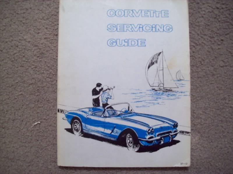
First of all, I'm not going to get down into the small details. Either the Corvette ST12 or the 49-54 Chevy passenger car manual have excellent instructions and illustrations. If you don't have one or both of them, then get them, especially if you plan to do most of the work, manitenance and repairs to the car yourself.
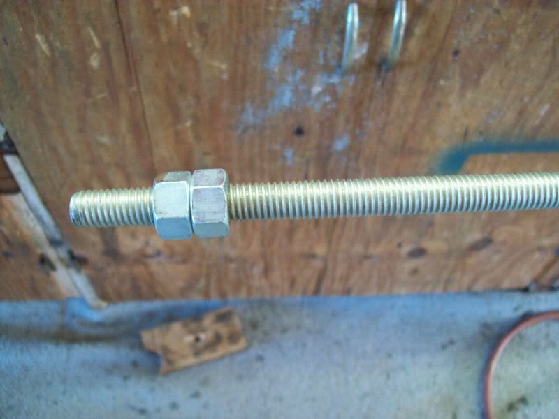
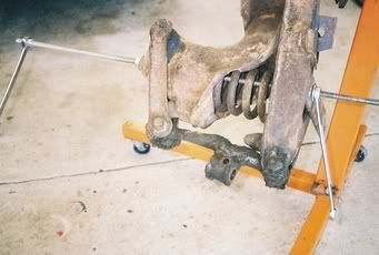
For a total teardown and rebuild, one of the first things to do is remove the coil springs. A 3ft length of 1/2in all thread rod with flat washers and nuts is a very cheap tool and works well to compress the springs.
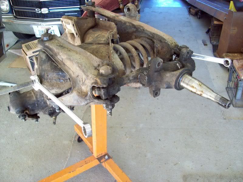
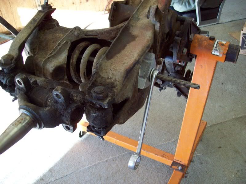
I lock two nuts together on one end of the rod which allows holding the rod securely with a wrench. Although, if desired, just one nut could be welded to one end of the rod.
Once the spring is compressed, the LOWER-OUTER shaft (or bolt if you prefer) can be removed to seperate the spindle support from the lower A-frame.
Prior to seperating the spindle support from the lower A-frame, it may be desired to seperate the spindle from the spindle support. It really doesn't matter if the spindle/support are seperated at this time, or after the support is removed from the A-frames and then seperated on the workbench, it's a toss up.
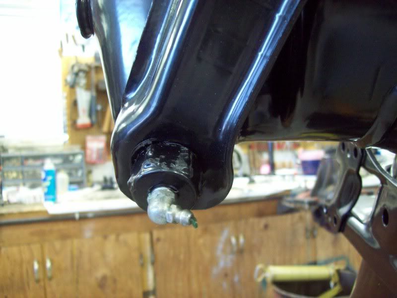
After removal of the spindles and spindle supports and a little cleaning, these yellow and orange paint markings were discovered on the parts. These paint markings were obviously applied on the parts prior to assembly (probably after final machining of individual parts) and prior to application of black paint (which of course would conceal the paint markings).
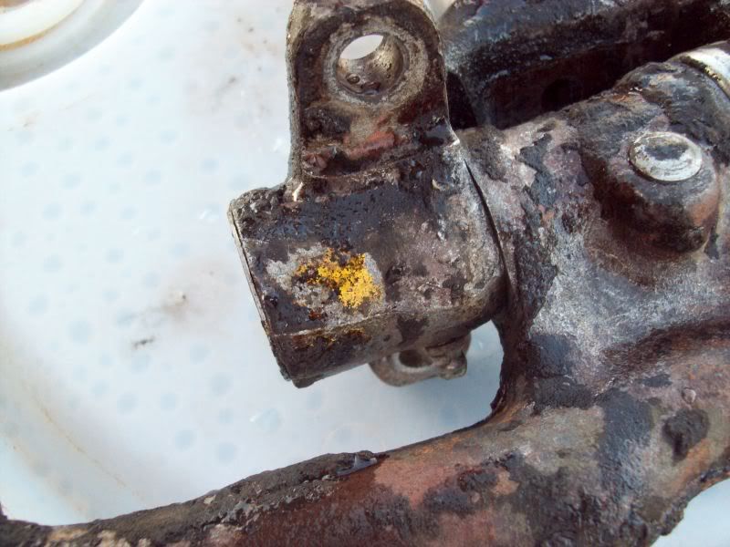
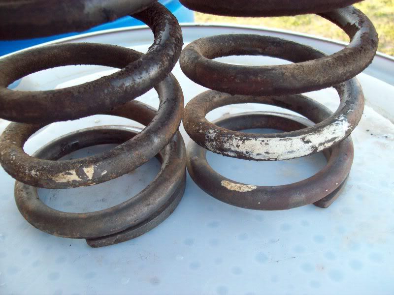
Also, after removal of the (stock) spings, this white paint markings was revealed.
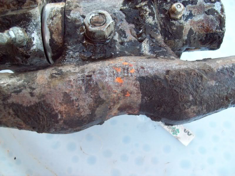
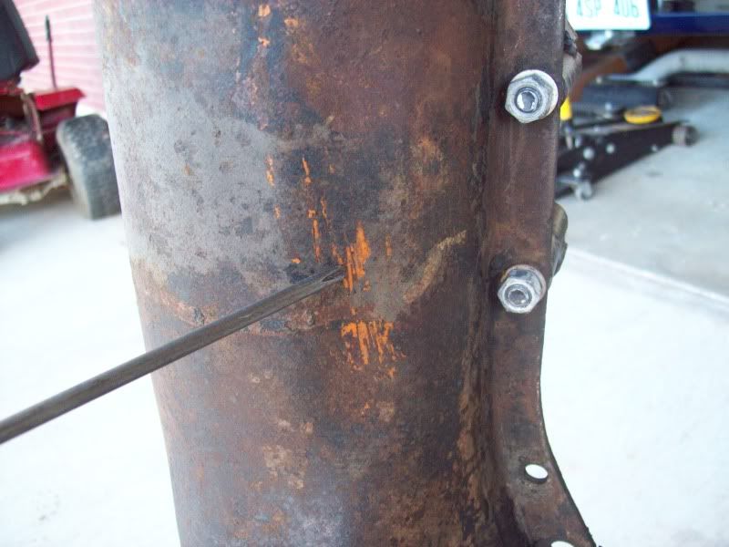
This orange paint was also revealed on the cross member.
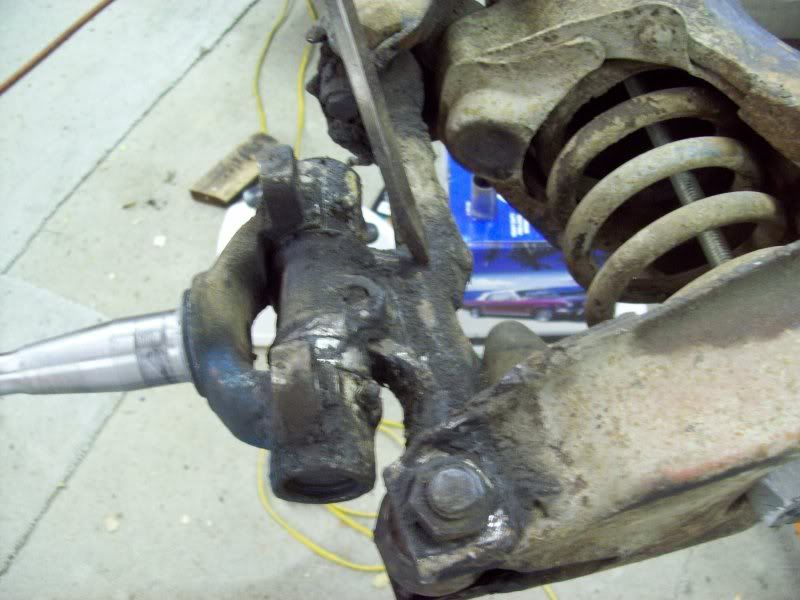
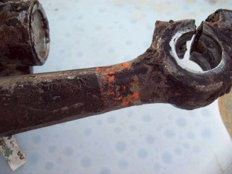
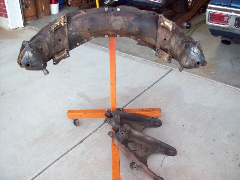
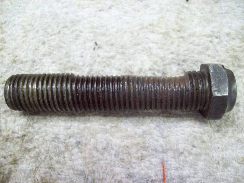
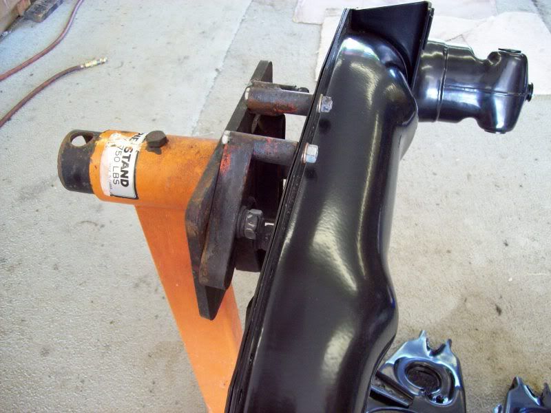
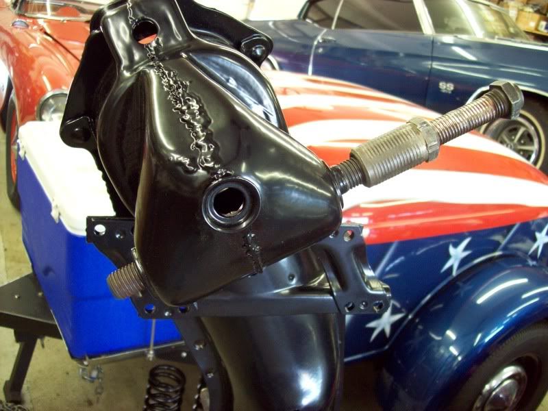
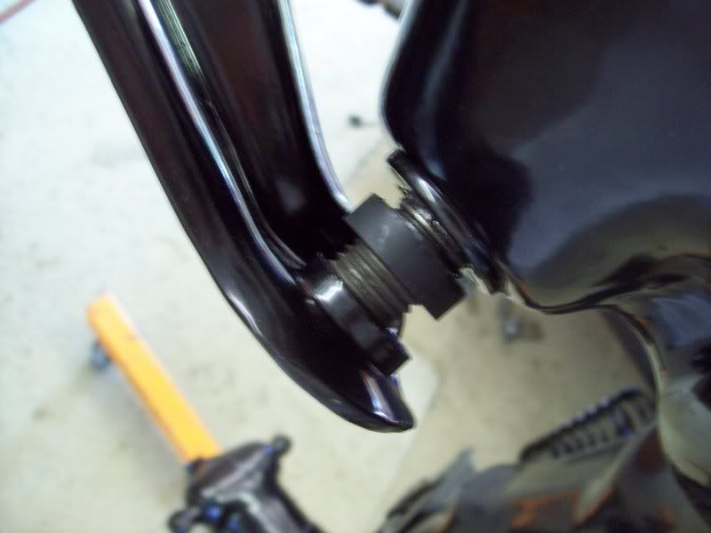
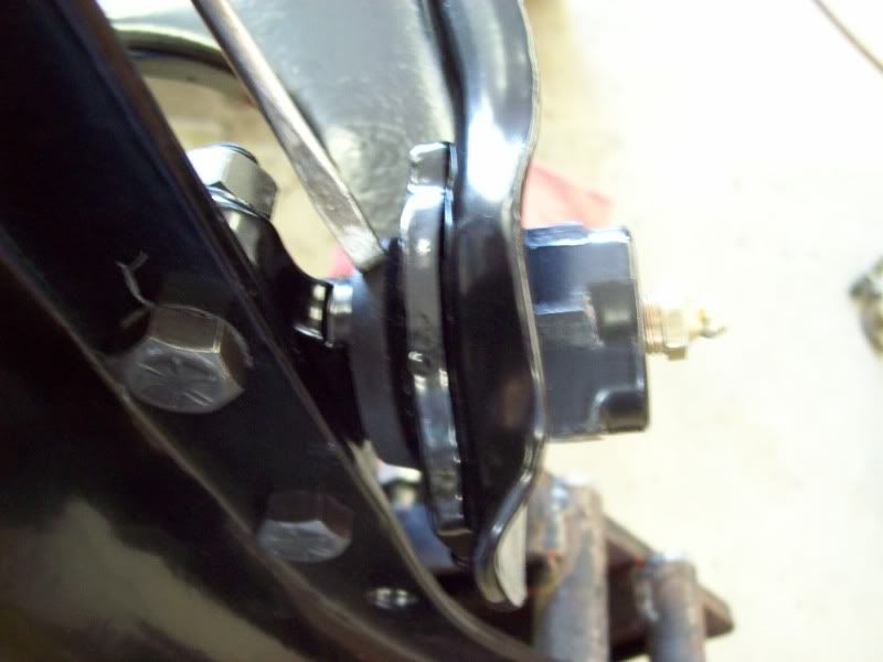
Once the cross member is completely disassembled, all that remains are the UPPER-INNER cross shafts, which are VERY tightly threaded into the cross member.
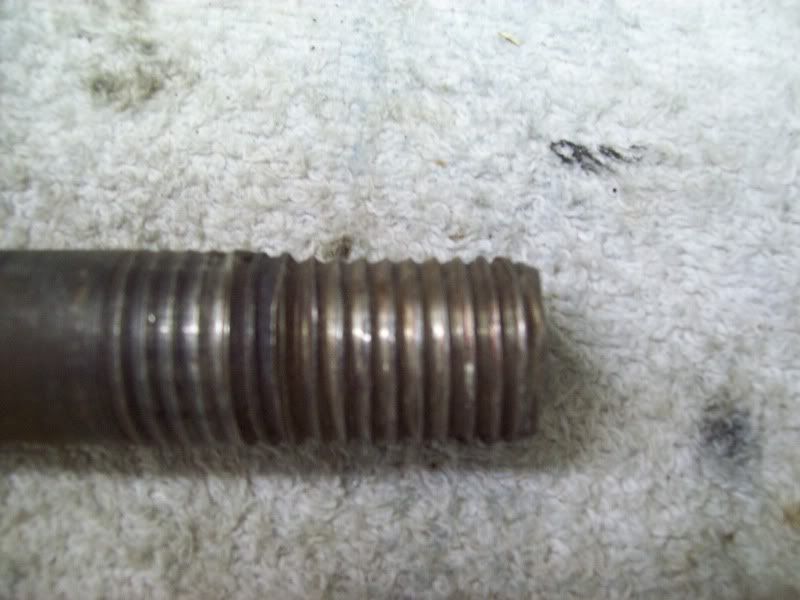
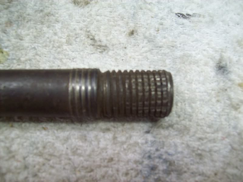
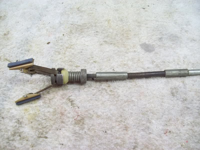
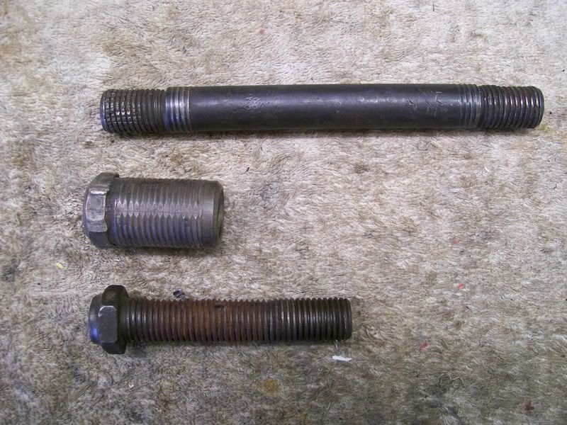
Examine the threads on each end of the shafts. If they are worn like this, then the threads inside bushings will also be worn and the shaft/bushings need to be replaced.
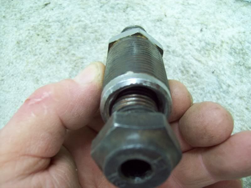
There are essentially two ways to remove these shafts. Either with a BIG pipe wrench, which will permanently damage the threads on one end, or, using the tool shown in the manual.
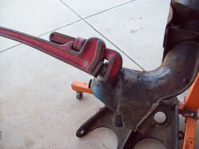
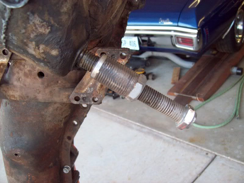
There is no need to search all over trying to find the tool. The tool for removing/installing the the upper-inner shafts is already at your finger tips. The LOWER-OUTER bushing and shaft makes a perfect tool. Screw the outer-lower shaft/bushing onto the REAR of the upper-inner shaft and screw it out of the cross member torward the FRONT. If the upper-inner shaft is still tight in the cross member (ideally it will be), then it may take some muscle to get it to start unscrewing from the cross member.
It's not uncommon to discover that the upper-inner shaft is sloppy loose in the welded-in bushings due to poor past maintenance (failure to keep the suspension joints greased).
But here is where we start
And here is where we finish.
The frontend rebuild in the following pictures is from a 57 Corvette which appeared to have never been rebuilt. Also, it is very representative of all 49-54 Chevy passenger car and 53-62 Corvettes.
First of all, I'm not going to get down into the small details. Either the Corvette ST12 or the 49-54 Chevy passenger car manual have excellent instructions and illustrations. If you don't have one or both of them, then get them, especially if you plan to do most of the work, manitenance and repairs to the car yourself.
For a total teardown and rebuild, one of the first things to do is remove the coil springs. A 3ft length of 1/2in all thread rod with flat washers and nuts is a very cheap tool and works well to compress the springs.
I lock two nuts together on one end of the rod which allows holding the rod securely with a wrench. Although, if desired, just one nut could be welded to one end of the rod.
Once the spring is compressed, the LOWER-OUTER shaft (or bolt if you prefer) can be removed to seperate the spindle support from the lower A-frame.
Prior to seperating the spindle support from the lower A-frame, it may be desired to seperate the spindle from the spindle support. It really doesn't matter if the spindle/support are seperated at this time, or after the support is removed from the A-frames and then seperated on the workbench, it's a toss up.
After removal of the spindles and spindle supports and a little cleaning, these yellow and orange paint markings were discovered on the parts. These paint markings were obviously applied on the parts prior to assembly (probably after final machining of individual parts) and prior to application of black paint (which of course would conceal the paint markings).
Also, after removal of the (stock) spings, this white paint markings was revealed.
This orange paint was also revealed on the cross member.
Once the cross member is completely disassembled, all that remains are the UPPER-INNER cross shafts, which are VERY tightly threaded into the cross member.
Examine the threads on each end of the shafts. If they are worn like this, then the threads inside bushings will also be worn and the shaft/bushings need to be replaced.
There are essentially two ways to remove these shafts. Either with a BIG pipe wrench, which will permanently damage the threads on one end, or, using the tool shown in the manual.
There is no need to search all over trying to find the tool. The tool for removing/installing the the upper-inner shafts is already at your finger tips. The LOWER-OUTER bushing and shaft makes a perfect tool. Screw the outer-lower shaft/bushing onto the REAR of the upper-inner shaft and screw it out of the cross member torward the FRONT. If the upper-inner shaft is still tight in the cross member (ideally it will be), then it may take some muscle to get it to start unscrewing from the cross member.
It's not uncommon to discover that the upper-inner shaft is sloppy loose in the welded-in bushings due to poor past maintenance (failure to keep the suspension joints greased).
Last edited by DZAUTO; 05-31-2009 at 06:52 PM.
 05-31-2009, 03:30 PM
#2
Race Director
Thread Starter
Member Since: Mar 2001
Location: Mustang OK
Posts: 13,852
Received 3,773 Likes
on
1,674 Posts
2023 C1 of the Year Finalist - Modified
2015 C1 of the Year Finalist
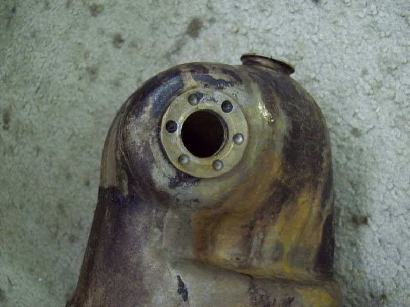
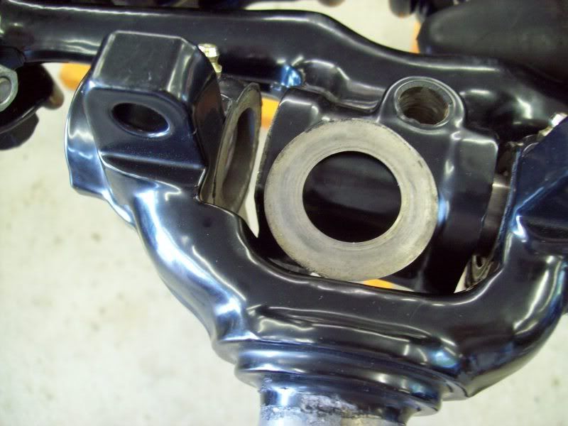
If it is discovered that the hole(s) in these bushings are enlarged, then the new shaft will never be tight in the cross member. These bushings are available for replacement from Paragon. To replace these bushings, drill out the spot welds to remove the old bushings and weld in new bushings per the instructions which come with the new bushings from Paragon. NOTICE: THE THREADED HOLES IN THE BUSHINGS ARE TWO DIFFERENT SIZES (as well as the threads on the new cross shafts)! The bushing with the smaller hole goes to the rear of the cross member and the bushing with the larger hole goes to the front!
If needed, this repair must be done before proceeding any further with the rebuild.
If the rebuild is to be done with the cross member on the car, this particular repair may be quite challenging to install and weld in place the rear bushing. Thus, it will be imperative to have access to a welder prior to teardown of the suspension parts.
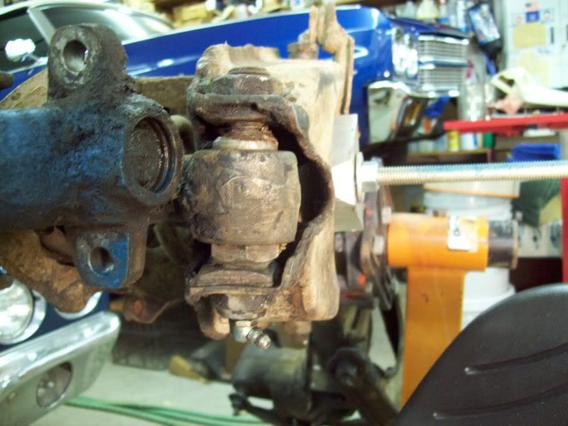
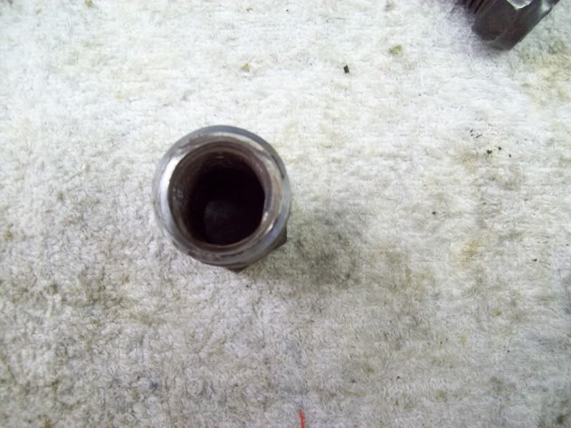
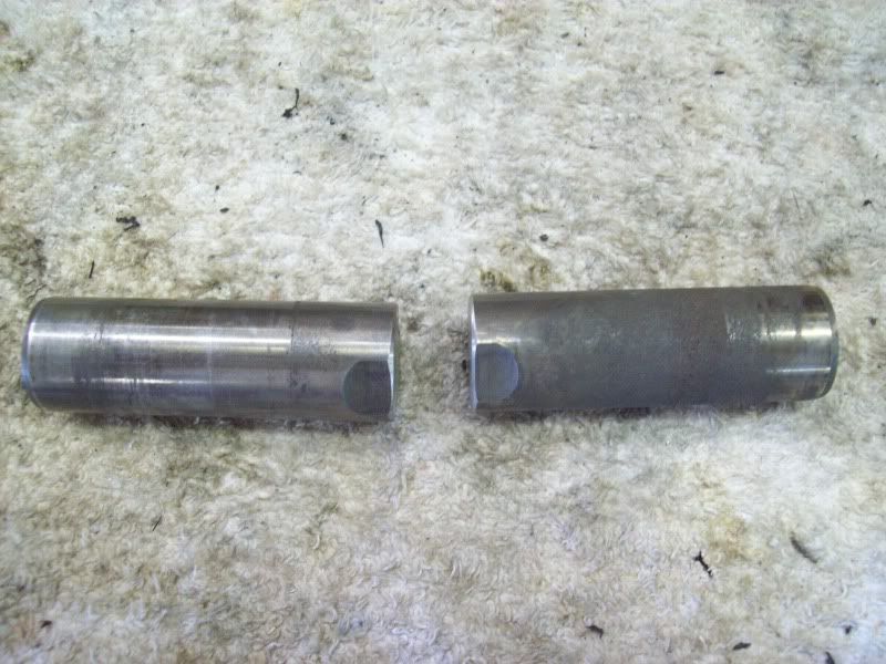
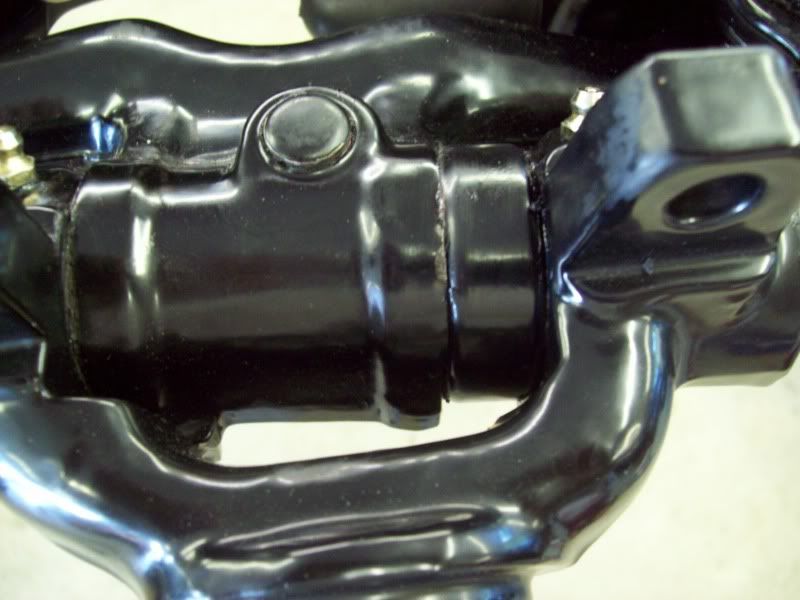
Another common area of wear is the LOWER-OUTER shaft/bushing. Here is a well worn shaft and bushing. All of these parts are available from the vendors, either individually, or as complete rebuild kits. Sometimes, removal of the old bushing from the spindle support can be quite difficult. It may be necessary to soak it for long periods and/or use heat. But I've never seen one that couldn't be removed from the lower hole of the spindle support.
Once all the parts are broken down, the next step is cleaning, painting and re-assembly of the cross member/suspension. This becomes a personal decision on the part of the owner. The following is what was done to this 57 Corvette cross member/suspension.
First, every part had as much gunk scraped off as possible. Then a VERY strong commercial degreaser was used (oven cleaner also makes an excellent cleaner) and allowed to soak for 15-30min. Some areas required 2-3 applications to get down to bare metal (often much of the parts will have surface rust). Once the parts are cleaned, I soak them in a big barrel of muratic acid (Hydorchloric acid) which is available in gallon jugs at any hardware store (Lowes, Home Depot, Aces, etc) for $5-7/gal. I dilute the acid about 1:3 with water.
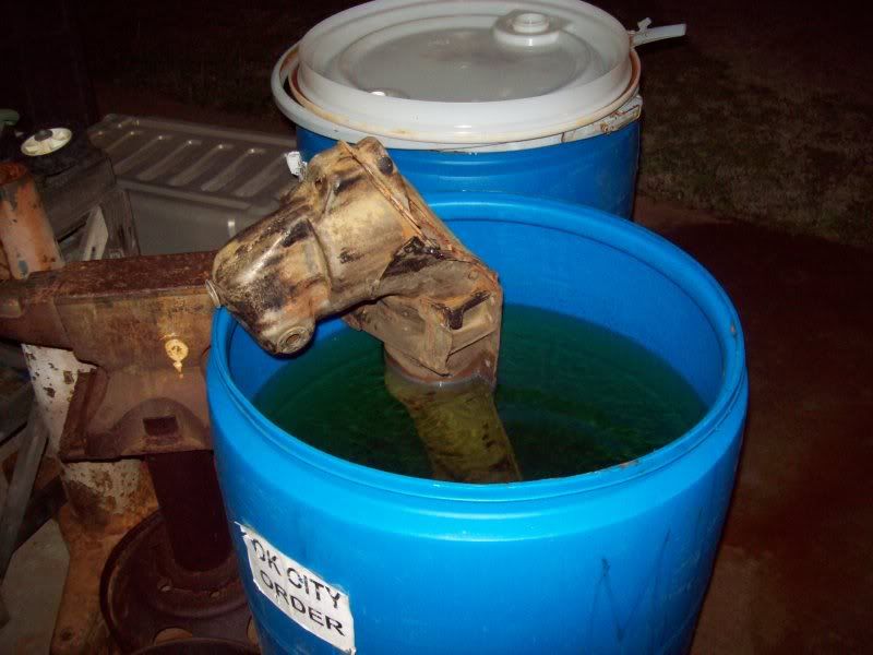
After removing parts from the acid, they are THOROUGHLY rinsed off with a power washer (BE SURE to rinse well inside the cross member) using VERY hot water (my hot water heater is turned up to the max). After thorough rinsing, all parts are blasted to finally get them to bare metal.
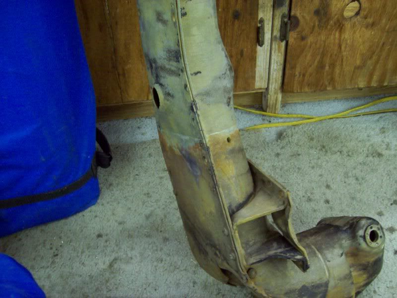
AFTER ACID DIPPING, AND BEFORE BLASTING
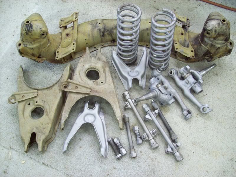
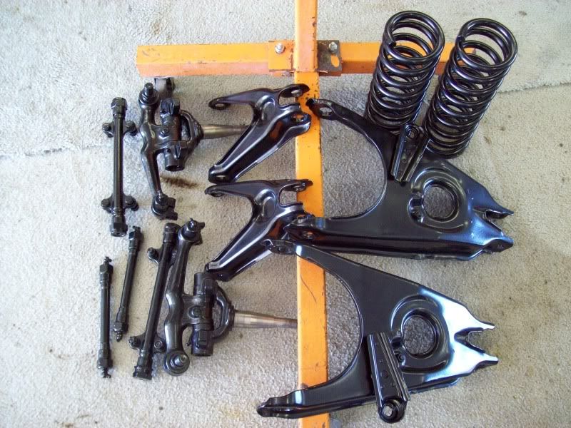
SOME PARTS BLASTED
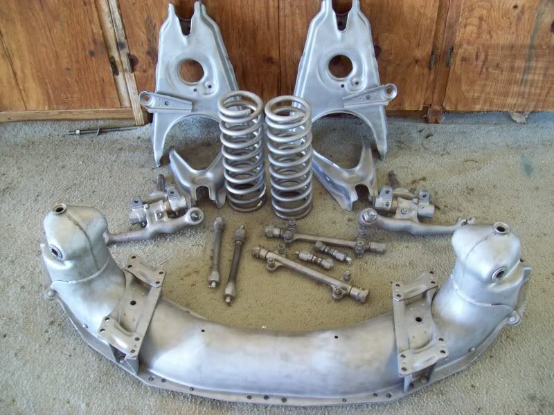
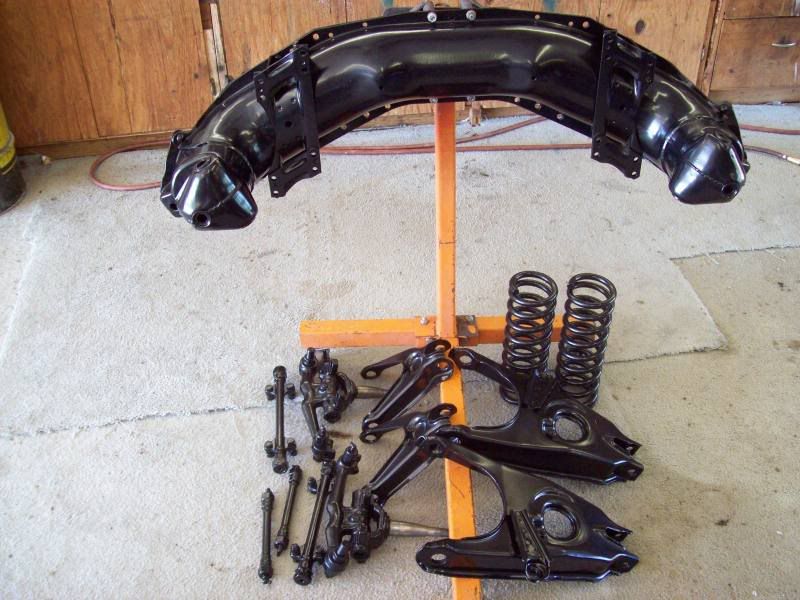
ALL PARTS BLASTED AND READY FOR PAINT, POWDER COAT, ETC
One process that may be required prior to paint/powder coating, is fitting the bushings for the kingpins into the spindles. The bushings are supposed to be FLOATING, NOT pressed-in!!! At one time, replacement kingpin/bushing kits were furnished with floating bushings. But the last several kits that I've purchased did NOT have floating bushings. A floating bushing, with LIGHT lubrication, should just be a slip fit into the bores of the spindle. None of the recent ones I've bought were!
I've not found a satisfactory method of reducing the outer diameter of the replacement bushings, so, I devised a simple method of honing the bores of the spindles.
I use a 3-stone wheel cylinder hone and hone the bores IN WATER using an AIR powered drill (please don't use an elec drill!). Submerging the spindle in a 5gal bucket of water while honing works fine. I do it under running water. I continually hone and check the bushing for a slip fit, until a "just right" slip fit is achieved. IT IS IMPORTANT TO CONTINUALLY RUN THE HONE UP AND DOWN IN THE BORE SO THAT AN UNEVEN DIAMETER DOES NOT OCCUR!!! The bushing should not drop through the bore, but with light finger pressure, it should gently slide through the bore.
After everything is disassembled, cleaned, acid dipped, blasted and any repairs are completed, the parts (per individual preference) are now ready for painting, powder coating or whatever you choose.
These parts were powder coated semi-gloss black. Some areas need to be covered with tape such as spindle ends, threaded areas, etc. Most powder coating businesses will do this as directed.
Now its time to begin assembly of all the finished parts. MOST of the assembly process is covered very well in the ST12/49-54 pass car manuals. Much of what will be covered is somewhat supplemental.
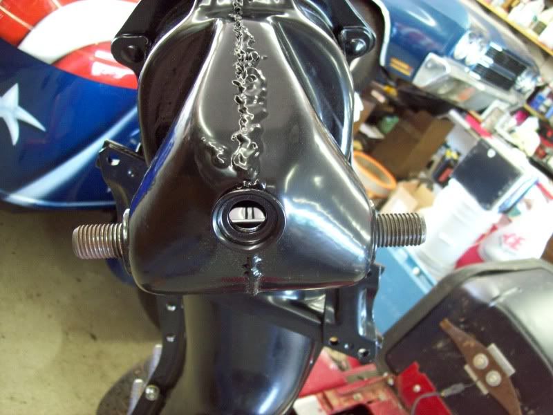
The first parts to install are the new, upper-inner shafts.
NOTICE: THESE SHAFTS HAVE 2 DISTINCT SETS OF THREADS (inner and outer).
The finer, outer threads are for the bushings (big nuts screwed into the upper A-frames), and the lesser defined inner threads are screwed into the bushings in the cross member. New shafts have approximately .008 oversize threads for the cross member holes, thus, they are VERY HARD to screw into the cross member. If the old, removed bushing/shaft are excessively worn, then each of the new bushing/shaft can be used as an installation tool. Only use ONE new bushing/shaft to install each upper-inner shaft, then use the other new bushing/shaft to install the other new upper-inner shaft. Screw the lower-outer shaft into the bushing far enough to allow the bushing to screw onto MOST of the threads of the new upper-outer shaft. REMEMBER, the SMALL portion of the threads which screw into the cross member goes in first FROM THE FRONT! THIS IS CRITICALLY IMPORTANT!!
For installing the new shafts, use an old lower-outer bushing and shaft.
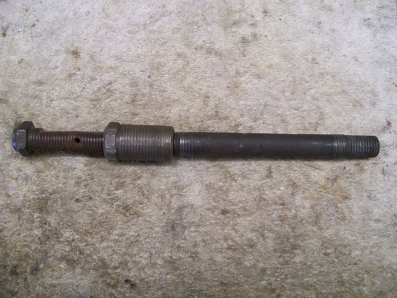
As mentioned above, installing the new upper-inner shafts is a VERY tight fit since they are oversize. Install them dry, do not use any lubricant. These shafts need to fit so tight that there will not be any possible chance of them turning in the cross member bushings.
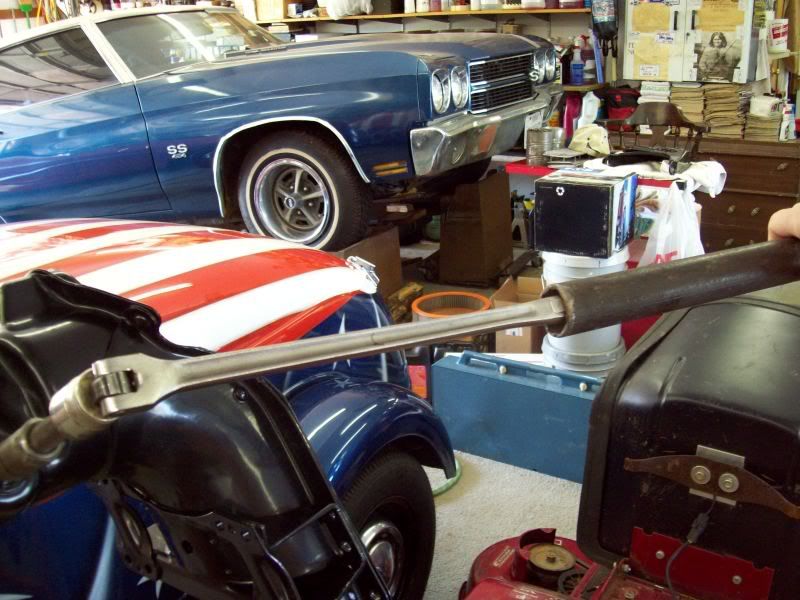
A breaker bar and "cheater" may be required to get the shafts installed.
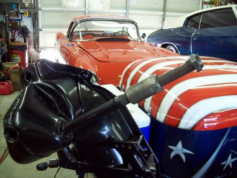
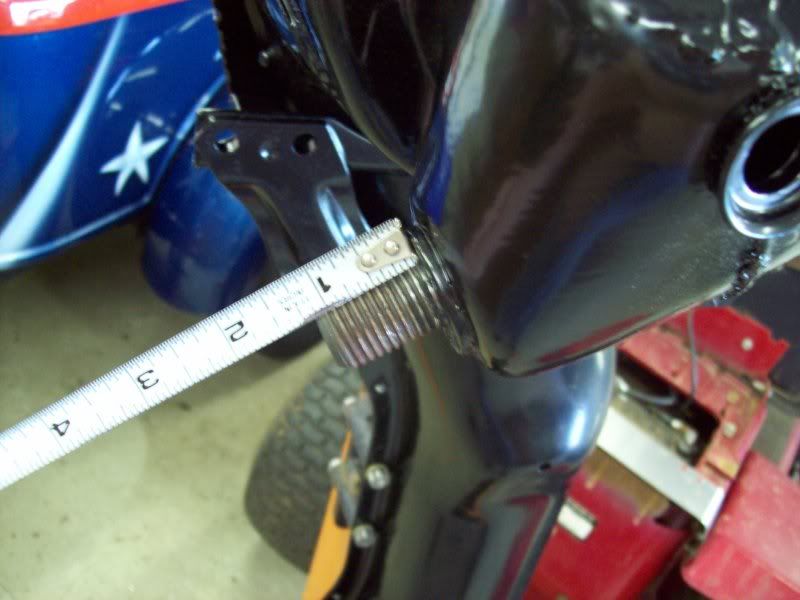
Once the shafts are installed most of the way, start measuring each end to assure they have equal length threads protruding from each side. Again, critically important!
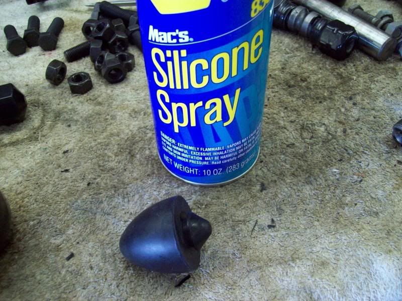
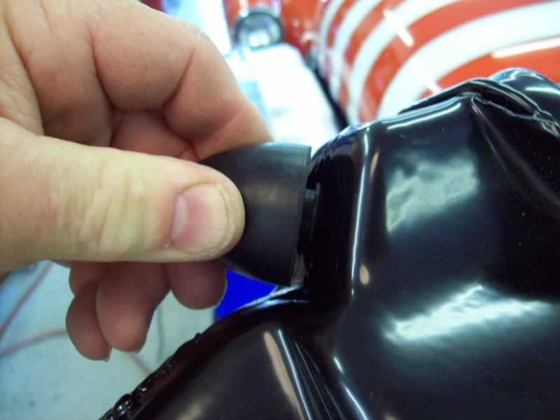
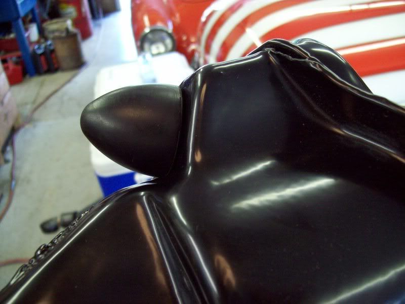
Little things, such as installing the new rubber bumpers for the upper A-frames, are good to do now. Spray a little silicon on the end, insert it at an angle into the hole and with a pushing, twisting motion, twist it into the hole.
If needed, this repair must be done before proceeding any further with the rebuild.
If the rebuild is to be done with the cross member on the car, this particular repair may be quite challenging to install and weld in place the rear bushing. Thus, it will be imperative to have access to a welder prior to teardown of the suspension parts.
Another common area of wear is the LOWER-OUTER shaft/bushing. Here is a well worn shaft and bushing. All of these parts are available from the vendors, either individually, or as complete rebuild kits. Sometimes, removal of the old bushing from the spindle support can be quite difficult. It may be necessary to soak it for long periods and/or use heat. But I've never seen one that couldn't be removed from the lower hole of the spindle support.
Once all the parts are broken down, the next step is cleaning, painting and re-assembly of the cross member/suspension. This becomes a personal decision on the part of the owner. The following is what was done to this 57 Corvette cross member/suspension.
First, every part had as much gunk scraped off as possible. Then a VERY strong commercial degreaser was used (oven cleaner also makes an excellent cleaner) and allowed to soak for 15-30min. Some areas required 2-3 applications to get down to bare metal (often much of the parts will have surface rust). Once the parts are cleaned, I soak them in a big barrel of muratic acid (Hydorchloric acid) which is available in gallon jugs at any hardware store (Lowes, Home Depot, Aces, etc) for $5-7/gal. I dilute the acid about 1:3 with water.
After removing parts from the acid, they are THOROUGHLY rinsed off with a power washer (BE SURE to rinse well inside the cross member) using VERY hot water (my hot water heater is turned up to the max). After thorough rinsing, all parts are blasted to finally get them to bare metal.
AFTER ACID DIPPING, AND BEFORE BLASTING
SOME PARTS BLASTED
ALL PARTS BLASTED AND READY FOR PAINT, POWDER COAT, ETC
One process that may be required prior to paint/powder coating, is fitting the bushings for the kingpins into the spindles. The bushings are supposed to be FLOATING, NOT pressed-in!!! At one time, replacement kingpin/bushing kits were furnished with floating bushings. But the last several kits that I've purchased did NOT have floating bushings. A floating bushing, with LIGHT lubrication, should just be a slip fit into the bores of the spindle. None of the recent ones I've bought were!
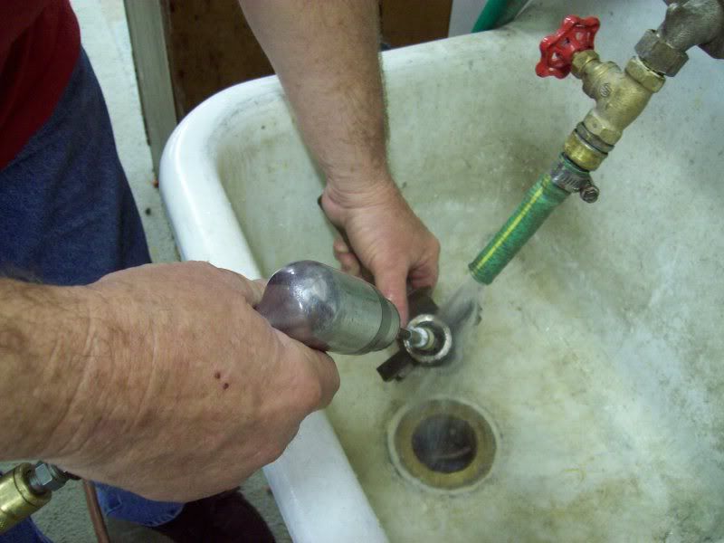
I've not found a satisfactory method of reducing the outer diameter of the replacement bushings, so, I devised a simple method of honing the bores of the spindles.
I use a 3-stone wheel cylinder hone and hone the bores IN WATER using an AIR powered drill (please don't use an elec drill!). Submerging the spindle in a 5gal bucket of water while honing works fine. I do it under running water. I continually hone and check the bushing for a slip fit, until a "just right" slip fit is achieved. IT IS IMPORTANT TO CONTINUALLY RUN THE HONE UP AND DOWN IN THE BORE SO THAT AN UNEVEN DIAMETER DOES NOT OCCUR!!! The bushing should not drop through the bore, but with light finger pressure, it should gently slide through the bore.
After everything is disassembled, cleaned, acid dipped, blasted and any repairs are completed, the parts (per individual preference) are now ready for painting, powder coating or whatever you choose.
These parts were powder coated semi-gloss black. Some areas need to be covered with tape such as spindle ends, threaded areas, etc. Most powder coating businesses will do this as directed.
Now its time to begin assembly of all the finished parts. MOST of the assembly process is covered very well in the ST12/49-54 pass car manuals. Much of what will be covered is somewhat supplemental.
The first parts to install are the new, upper-inner shafts.
NOTICE: THESE SHAFTS HAVE 2 DISTINCT SETS OF THREADS (inner and outer).
The finer, outer threads are for the bushings (big nuts screwed into the upper A-frames), and the lesser defined inner threads are screwed into the bushings in the cross member. New shafts have approximately .008 oversize threads for the cross member holes, thus, they are VERY HARD to screw into the cross member. If the old, removed bushing/shaft are excessively worn, then each of the new bushing/shaft can be used as an installation tool. Only use ONE new bushing/shaft to install each upper-inner shaft, then use the other new bushing/shaft to install the other new upper-inner shaft. Screw the lower-outer shaft into the bushing far enough to allow the bushing to screw onto MOST of the threads of the new upper-outer shaft. REMEMBER, the SMALL portion of the threads which screw into the cross member goes in first FROM THE FRONT! THIS IS CRITICALLY IMPORTANT!!
For installing the new shafts, use an old lower-outer bushing and shaft.
As mentioned above, installing the new upper-inner shafts is a VERY tight fit since they are oversize. Install them dry, do not use any lubricant. These shafts need to fit so tight that there will not be any possible chance of them turning in the cross member bushings.
A breaker bar and "cheater" may be required to get the shafts installed.
Once the shafts are installed most of the way, start measuring each end to assure they have equal length threads protruding from each side. Again, critically important!
Little things, such as installing the new rubber bumpers for the upper A-frames, are good to do now. Spray a little silicon on the end, insert it at an angle into the hole and with a pushing, twisting motion, twist it into the hole.
Last edited by DZAUTO; 05-31-2009 at 11:36 PM.
05-31-2009, 03:31 PM
#3
Race Director
Thread Starter
Member Since: Mar 2001
Location: Mustang OK
Posts: 13,852
Received 3,773 Likes
on
1,674 Posts
2023 C1 of the Year Finalist - Modified
2015 C1 of the Year Finalist
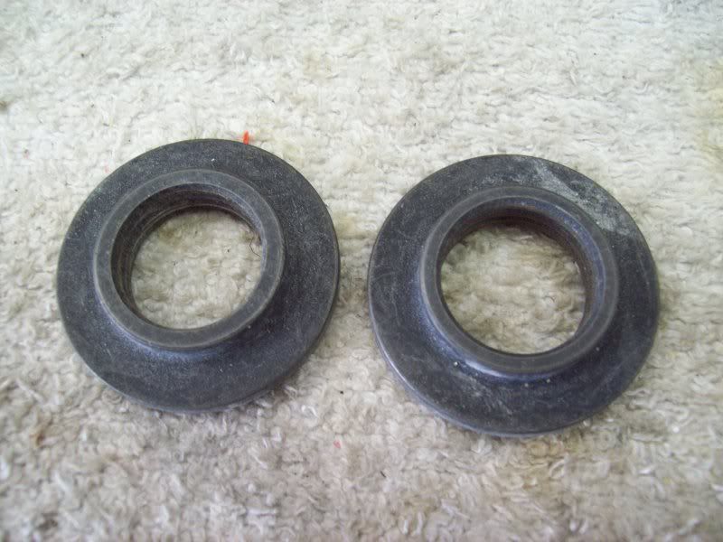
At each joint, there is some kind of rubber seal which goes over the shaft threads to keep crud out of the shaft/bushing seals. The rebuild kits may or may not come with good seals and Paragon has a kit containing all the needed seals for a complete frontend.
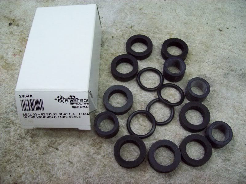
Prior to installing the upper A-frame, slide a seal over each end of the shaft threads, slip one end of the A-frame over the shaft then slip the other end of the A-frame over the shaft. With the seals in place, it may take some concentrated tugging on the other end of the A-frame to get it pulled over the shaft.
Coat the threads of the shaft with grease, then start each bushing evenly over the threaded shaft until the ends of the bushings contact the A-frame, making sure the A-frame is centered. Where the bushing screws into the A-frame, it needs to be dry, not lubed. Then screw each bushing, a little at a time, all the way into the A-frame, continually checking that the A-frame remains centered.
ALL grease fittings for the front end are straight, EXCEPT the REAR, upper A-frame grease fitting. It is either a 45deg or 90deg fitting (I've observed both styles over the years). Install the upper, rear fitting so that it points downward and slightly outward when the A-frame is in a normal loaded position.
Installing the lower A-frame can be done by either attaching the cross shaft to the cross member, or, by installing the cross shaft to the lower A-frame and then bolting the shaft to the cross member.
I prefer to install the shaft to the cross member first-----WITH NEW GRADE 8 BOLTS!
Similar to installing the upper A-frame, place one seal on one end of the shaft, then slip one end of the lower A-frame over the shaft (the end without a seal) and then slip the other end over the shaft (it's often nearly impossible to pull the other end over the shaft if both seals are installed. I have found it easier to only install one seal, slip on the A-frame, then grease and slip on the second seal over the shaft and CAREFULLY and PATIENTLY poke the seal through the gap between the A-frame hole and the shaft with a screw driver. Apply some grease onto the threads of each end of the shaft and start the bushings onto each end of the shaft, and again, make sure the lower A-frame is centered. So not use any lube on the bushings where they screw into the lower A-frame. The new bushings may screw in very tightly, that's how they should be. Screw them in all the way.
After the upper and lower A-frames are installed on their shafts, install grease fittings, shoot some grease into the bushings and work the A-frames back up and down and shoot in some more grease. Now is also a good time to install the rubber bumper in the lower A-frame if not already installed.
Now it's time to install the springs and the spindle supports.
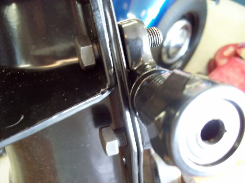
I prefer to first install the UPPER end of the spindle support in the upper A-frame with the upper-outer excentric shaft and bushings. The upper-outer shaft has a hole all the way through it and one end of the hole has a hex for turning with an Allen wrench. Only one of the upper-outer bushings has a hole for a grease fitting. The hole in the shaft with the hex and the bushing with a hole go toward the REAR. Slip the lock bolt for the upper-outer shaft in position to keep the shaft centered in the spindle support screw on the nut and lock washer loosely. At this time, I only screw on the upper bushings loosely onto the shaft to allow flexibility for positioning and installing the lower-outer shaft. If installing a new lower-outer bushing/shaft, the bushing should already be installed in the spindle support.
The springs only go in ONE WAY, up and down and rotational. The flat end of the springs goes up into the pocket of the cross member and the lower end of each spring is indexed in the lower A-frame with the end of the coil positioned just over the drain hole.
Slip the length of all thread through the lower A-frame, spring and the hole in the cross member for the upper end of the shock and begin pulling everything together.
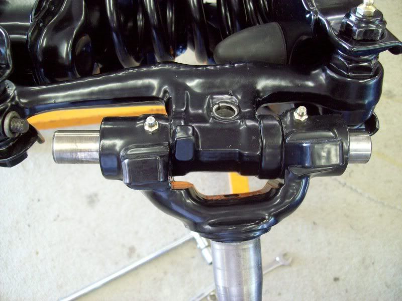
It can be a challenge, but a seal needs to be installed on EACH SIDE of the lower end of the spindle support for the lower-outer shaft. I prefer to partially screw in the lower shaft then hand one seal on the end of the shaft, then slip lower end of the spindle support, along with the second seal, between the holes of the A-frame and then finish screwing in the shaft. The lower-outer shaft can go in either from the front or rear. From the majority of cars I've observed, and illustrations in the manual, it definitely appears the lower-outer shaft screws in from the rear with the grease fitting facing the rear. Sometimes, after the lower shaft has gone all the way through the spindle support, it may or may not want ot properly screw into the other side of the A-frame. A large C-clamp can be used to squeeze the A-frame together to assist in getting the shaft to properly screw into the other side of the A-frame. Screw the shaft in completely and very tightly, then screw on the lock nut very tight.
Once both ends of the spindle support are scured, the upper bushings can be completely screwed into the upper A-frame and an Allen wrench can be inserted to center the spindle support.
Now the length of all thread can be removed.
The final part of assembly is installing the spindles onto the spindle supports with new kingpins and bushings. Earlier, honing the bores for a slip of the bushings was explained. Each bushing has a hole for grease to enter the bushing. This hole is positioned in the spindle bores opposite of the hole for the grease fitting. When bushings get greased, the grease is supposed to go all around the bushing and then into the inside to lube the kingpin.
To make it easier to assemble the spindle, kingpins, bushings and spindle support, take an old kingpin and cut it in half (I use a die grinder and thin cutoff wheel to cut one).
A test fit of the spindle, bushings, kingpin, thrust bearing and spindle support may be required 2-3 times to get it right. The BOOK instructs to do this one way, I was taught another way. After years of experience, I prefer my way for a good reason.
First, pack the thrust bearings with grease.
Place the spindle with the bushings inserted (lightly lube the inside and outside diameters of the bushings) over the knuckle of the spindle support, slide a kingpin all the way through the assembly until it protrudes from the upper end enough to allow the thrust bearing to be installed between the knuckle and lower end of the spindle. The thrust bearing is installed with the gap between inner and outer races facing down. Once the bearing is properly positioned, tap the kingpin back in all the way. This is where the book and I differ. The book shows inserting a feeler gauge to check the gap. If the gap is more than .006, a shim is needed. I was taught (by a factory trained Chevy mechanic, my uncle) that once the spindle is assembled to the spindle support, it should be somewhat still to rotate the spindle. If it rotates easily, it's too loose and a shim is needed. Usually one, and no more than two shims are sufficient. The shims go on the upper end and the thrust bearing goes on the bottom.
If it is determined that a shim is needed, this is where the 1/2 of a kingpin is needed.
Remove the kingpin and pull the spindle off. Insert a shim between the upper bore of the spindle and the knuckle of the support. Slide the 1/2 kingpin in from above (may be necessary to remove the lockbolt from the upper-outer shaft) to hold the shim in place. Insert the bearing in place. It should be necessary to tap the bearing in place using a soft hammer/mallet). Slide the new kingpin in all the way from below, pushing the 1/2 piece of kingpin out the top. Check to see if the spindle is now stiff to rotate back and forth. If the spindle is now stiff to rotate, you're good to go. If it is still kind of easy to rotate, a second shim is needed. Disassemble and install a second shim as above. When the kingpin is inserted for the final time, notice that the flat in the kingpin will be aligned with the hole in the knuckle of the spindle support so that the kingpin lockbolt can be installed.
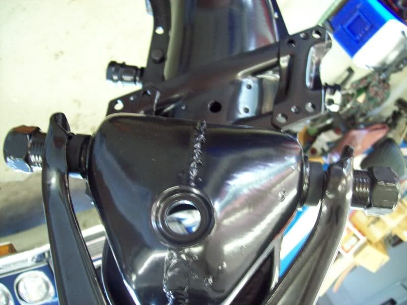
One side took one shim and the other side took 2 shims.
Everything assembled.
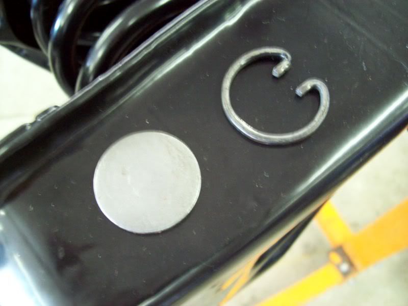
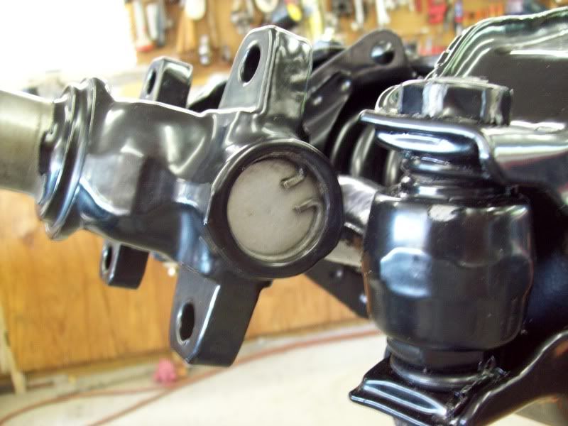
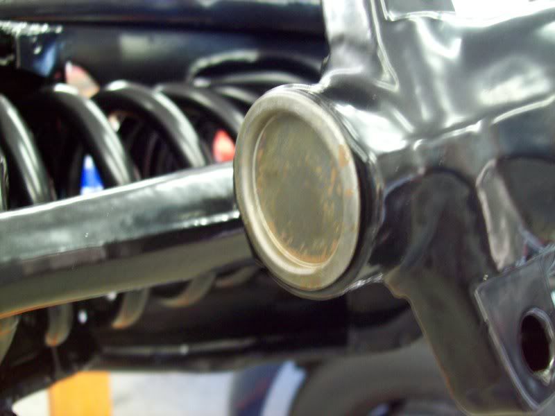
Once the spindle, kingpin, bushings, shims and bearing is assembled to the spindle support and you're satisfied the spindle rotates with the correct amount of stiffness (this is a subjective "feel" thing gained from experience), it's time to install the plugs and snap rings in each end of the bores.
After installing each plug (the convex side faces outward), but BEFORE installing the snap ring, lightly tap the plug to expand it tightly in its groove.
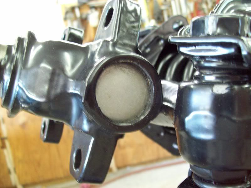
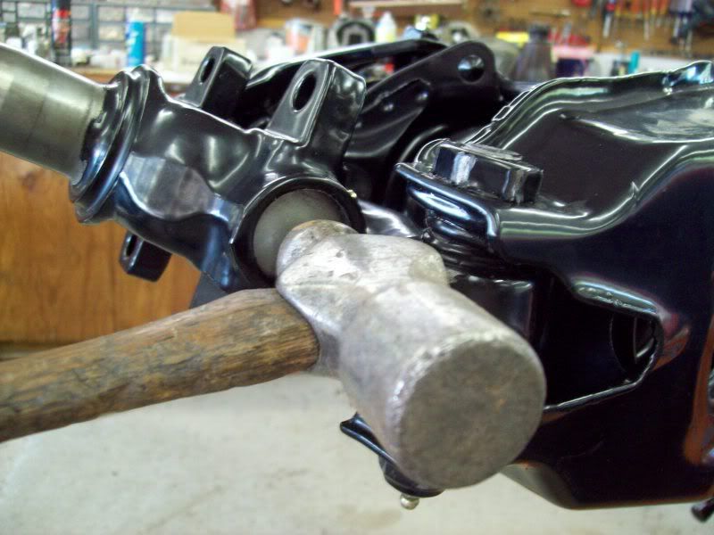
MOST kingpin/bushing kits contain two thin caps. This cap ONLY goes on the top of the spindle bore. It is necessary to gently tap it in place (they do not fit very tightly) and be careful not to deform it or it will never stay in place!
If all the grease fittings have not been screwed in place, do this now and thoroughly grease everything. After the assembled frontend is installed in the car and the weight of the car is on the suspension, bounce the car a few times and go back and grease everything.
I'm sure I've left out something,
Feel free to contact me with questions.
Tom Parsons
Prior to installing the upper A-frame, slide a seal over each end of the shaft threads, slip one end of the A-frame over the shaft then slip the other end of the A-frame over the shaft. With the seals in place, it may take some concentrated tugging on the other end of the A-frame to get it pulled over the shaft.
Coat the threads of the shaft with grease, then start each bushing evenly over the threaded shaft until the ends of the bushings contact the A-frame, making sure the A-frame is centered. Where the bushing screws into the A-frame, it needs to be dry, not lubed. Then screw each bushing, a little at a time, all the way into the A-frame, continually checking that the A-frame remains centered.
ALL grease fittings for the front end are straight, EXCEPT the REAR, upper A-frame grease fitting. It is either a 45deg or 90deg fitting (I've observed both styles over the years). Install the upper, rear fitting so that it points downward and slightly outward when the A-frame is in a normal loaded position.
Installing the lower A-frame can be done by either attaching the cross shaft to the cross member, or, by installing the cross shaft to the lower A-frame and then bolting the shaft to the cross member.
I prefer to install the shaft to the cross member first-----WITH NEW GRADE 8 BOLTS!
Similar to installing the upper A-frame, place one seal on one end of the shaft, then slip one end of the lower A-frame over the shaft (the end without a seal) and then slip the other end over the shaft (it's often nearly impossible to pull the other end over the shaft if both seals are installed. I have found it easier to only install one seal, slip on the A-frame, then grease and slip on the second seal over the shaft and CAREFULLY and PATIENTLY poke the seal through the gap between the A-frame hole and the shaft with a screw driver. Apply some grease onto the threads of each end of the shaft and start the bushings onto each end of the shaft, and again, make sure the lower A-frame is centered. So not use any lube on the bushings where they screw into the lower A-frame. The new bushings may screw in very tightly, that's how they should be. Screw them in all the way.
After the upper and lower A-frames are installed on their shafts, install grease fittings, shoot some grease into the bushings and work the A-frames back up and down and shoot in some more grease. Now is also a good time to install the rubber bumper in the lower A-frame if not already installed.
Now it's time to install the springs and the spindle supports.
I prefer to first install the UPPER end of the spindle support in the upper A-frame with the upper-outer excentric shaft and bushings. The upper-outer shaft has a hole all the way through it and one end of the hole has a hex for turning with an Allen wrench. Only one of the upper-outer bushings has a hole for a grease fitting. The hole in the shaft with the hex and the bushing with a hole go toward the REAR. Slip the lock bolt for the upper-outer shaft in position to keep the shaft centered in the spindle support screw on the nut and lock washer loosely. At this time, I only screw on the upper bushings loosely onto the shaft to allow flexibility for positioning and installing the lower-outer shaft. If installing a new lower-outer bushing/shaft, the bushing should already be installed in the spindle support.
The springs only go in ONE WAY, up and down and rotational. The flat end of the springs goes up into the pocket of the cross member and the lower end of each spring is indexed in the lower A-frame with the end of the coil positioned just over the drain hole.
Slip the length of all thread through the lower A-frame, spring and the hole in the cross member for the upper end of the shock and begin pulling everything together.
It can be a challenge, but a seal needs to be installed on EACH SIDE of the lower end of the spindle support for the lower-outer shaft. I prefer to partially screw in the lower shaft then hand one seal on the end of the shaft, then slip lower end of the spindle support, along with the second seal, between the holes of the A-frame and then finish screwing in the shaft. The lower-outer shaft can go in either from the front or rear. From the majority of cars I've observed, and illustrations in the manual, it definitely appears the lower-outer shaft screws in from the rear with the grease fitting facing the rear. Sometimes, after the lower shaft has gone all the way through the spindle support, it may or may not want ot properly screw into the other side of the A-frame. A large C-clamp can be used to squeeze the A-frame together to assist in getting the shaft to properly screw into the other side of the A-frame. Screw the shaft in completely and very tightly, then screw on the lock nut very tight.
Once both ends of the spindle support are scured, the upper bushings can be completely screwed into the upper A-frame and an Allen wrench can be inserted to center the spindle support.
Now the length of all thread can be removed.
The final part of assembly is installing the spindles onto the spindle supports with new kingpins and bushings. Earlier, honing the bores for a slip of the bushings was explained. Each bushing has a hole for grease to enter the bushing. This hole is positioned in the spindle bores opposite of the hole for the grease fitting. When bushings get greased, the grease is supposed to go all around the bushing and then into the inside to lube the kingpin.
To make it easier to assemble the spindle, kingpins, bushings and spindle support, take an old kingpin and cut it in half (I use a die grinder and thin cutoff wheel to cut one).
A test fit of the spindle, bushings, kingpin, thrust bearing and spindle support may be required 2-3 times to get it right. The BOOK instructs to do this one way, I was taught another way. After years of experience, I prefer my way for a good reason.
First, pack the thrust bearings with grease.
Place the spindle with the bushings inserted (lightly lube the inside and outside diameters of the bushings) over the knuckle of the spindle support, slide a kingpin all the way through the assembly until it protrudes from the upper end enough to allow the thrust bearing to be installed between the knuckle and lower end of the spindle. The thrust bearing is installed with the gap between inner and outer races facing down. Once the bearing is properly positioned, tap the kingpin back in all the way. This is where the book and I differ. The book shows inserting a feeler gauge to check the gap. If the gap is more than .006, a shim is needed. I was taught (by a factory trained Chevy mechanic, my uncle) that once the spindle is assembled to the spindle support, it should be somewhat still to rotate the spindle. If it rotates easily, it's too loose and a shim is needed. Usually one, and no more than two shims are sufficient. The shims go on the upper end and the thrust bearing goes on the bottom.
If it is determined that a shim is needed, this is where the 1/2 of a kingpin is needed.
Remove the kingpin and pull the spindle off. Insert a shim between the upper bore of the spindle and the knuckle of the support. Slide the 1/2 kingpin in from above (may be necessary to remove the lockbolt from the upper-outer shaft) to hold the shim in place. Insert the bearing in place. It should be necessary to tap the bearing in place using a soft hammer/mallet). Slide the new kingpin in all the way from below, pushing the 1/2 piece of kingpin out the top. Check to see if the spindle is now stiff to rotate back and forth. If the spindle is now stiff to rotate, you're good to go. If it is still kind of easy to rotate, a second shim is needed. Disassemble and install a second shim as above. When the kingpin is inserted for the final time, notice that the flat in the kingpin will be aligned with the hole in the knuckle of the spindle support so that the kingpin lockbolt can be installed.
One side took one shim and the other side took 2 shims.
Everything assembled.
Once the spindle, kingpin, bushings, shims and bearing is assembled to the spindle support and you're satisfied the spindle rotates with the correct amount of stiffness (this is a subjective "feel" thing gained from experience), it's time to install the plugs and snap rings in each end of the bores.
After installing each plug (the convex side faces outward), but BEFORE installing the snap ring, lightly tap the plug to expand it tightly in its groove.
MOST kingpin/bushing kits contain two thin caps. This cap ONLY goes on the top of the spindle bore. It is necessary to gently tap it in place (they do not fit very tightly) and be careful not to deform it or it will never stay in place!
If all the grease fittings have not been screwed in place, do this now and thoroughly grease everything. After the assembled frontend is installed in the car and the weight of the car is on the suspension, bounce the car a few times and go back and grease everything.
I'm sure I've left out something,
Feel free to contact me with questions.
Tom Parsons
Last edited by DZAUTO; 06-01-2009 at 08:40 AM.

 05-31-2009, 05:53 PM
#5


Tom that's a great rebuild. That should be in a manual. The photos are fantastic. Thanks for posting that I read every part of it and studies the photos. Thanks again Greg
05-31-2009, 06:05 PM
#6
Team Owner


Member Since: Oct 2000
Location: Washington Michigan
Posts: 38,899
Received 1,859 Likes
on
1,102 Posts
Outstanding, Tom - great job, great explanation and photos! 
05-31-2009, 07:07 PM
#9
Safety Car


Member Since: Apr 2009
Location: Georgetown TX
Posts: 3,789
Received 574 Likes
on
307 Posts
2021 C2 of the Year Finalist - Unmodified
C2 of Year Finalist (stock) 2019
2016 C2 of Year Finalist

Now this is the way to give step-by-step instructions with photos and first hand experience of doing it. Tom, you did a fine job and I hope others including myself learn from your experience. Corvette guys and gals are the best!
John
John
05-31-2009, 08:05 PM
#10
Burning Brakes

Tom,
If rest of the really hard parts of the restoration process could be presented like this, it would make one hell of a book.
Good job!
Larry
If rest of the really hard parts of the restoration process could be presented like this, it would make one hell of a book.
Good job!
Larry
 05-31-2009, 08:46 PM
#12
Instructor

Tom,
It's guys like you who are a cornerstone in making this site useful, accurate and informative. And in many ways so much better than the NCRS site. To say thanks for this and your other posts is insufficient in regard to the help you have given. But thanks nevertheless.
Reed
It's guys like you who are a cornerstone in making this site useful, accurate and informative. And in many ways so much better than the NCRS site. To say thanks for this and your other posts is insufficient in regard to the help you have given. But thanks nevertheless.
Reed

 05-31-2009, 11:45 PM
#14
Race Director
Thread Starter
Member Since: Mar 2001
Location: Mustang OK
Posts: 13,852
Received 3,773 Likes
on
1,674 Posts
2023 C1 of the Year Finalist - Modified
2015 C1 of the Year Finalist
If anyone is saving this, you may wish to go back and re-save it. I have edited a few errors that I've discovered.
Tom Parsons
Tom Parsons
06-01-2009, 03:40 AM
#15
Drifting


Tom thank you for sharing your valuable know how to us. I really appreciate your input on this forum 


 06-01-2009, 08:56 AM
#18
Burning Brakes

Member Since: Mar 2008
Location: Denver, CO
Posts: 1,038
Received 39 Likes
on
14 Posts
St. Jude Donor '08-'09-'10
great info. this is excellent!
having done kingpins in another vehicle... i just want to say THAT job sucks!
thanks for the time to write all this up and to document w/ pics
having done kingpins in another vehicle... i just want to say THAT job sucks!
thanks for the time to write all this up and to document w/ pics
06-01-2009, 10:51 AM
#19
Le Mans Master

Member Since: Feb 2004
Location: Norcal CA
Posts: 6,738
Received 554 Likes
on
447 Posts
2018 C1 of Year Finalist
Tom, great job! i could have used this quite awhile ago when I first put the front end together. I had to come up with a similar idea to compress the springs using a long stud pipe and blocks of wood since the spring compressor I had purchased did not fit properly. Great pictures and explanations!
