
DIY: Laguna Switch for NPP (C6)
 07-26-2014, 07:33 PM
#1
Intermediate

Thread Starter

Trying to get past sound at Laguna sucks. Period.
The limit is so low now (90db) that cars with factory exhaust regularly get pulled. In my case I blew 92.3db during my sound check at full tilt, of course I can lift out of turn 5 and skate by but thats annoying.
A fellow GS owner (thanks Richard!) back in march showed me a switch he uses to force the NPP flaps shut full time, which prevents him from getting ding'd for sound. As there's no DIY for this yet I thought I would write one.
Here's what we're going to build:
And here are the tools you need to do it (plus a bunch of extra stuff):
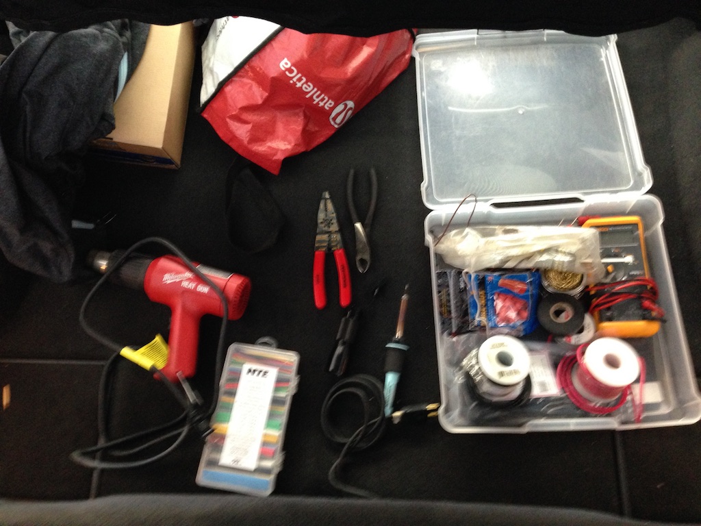
Tools, the detailed list:
There are also some optional "fancy" tools you can bring if you have them:
Background:
We use a diode here to prevent the BCM / ECM from getting cranky that we're powering the solenoids when they don't want us to. It doesn't trigger a light but it may log a fault code that a mechanic may misinterperet as a problem with your exhaust.
The ECM connector is always hot, that is to say it recieves B+ power directly from the battery (via the BCM) and in this configuration you'll have to remember to turn the switch off when not on track. I'm ok with this, but a better solution would be to use the power seat / seat heater fuse in the passenger compartment for a 12V supply that is switched to the ignition.
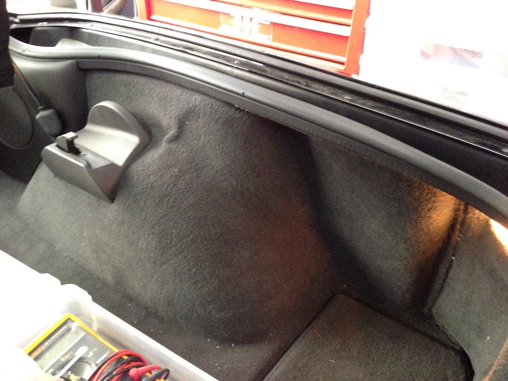
Step 1: Find and unplug the exhaust valve control module
First, disconnect the positive battery cable. Otherwise you'll blow a fuse when you try to splice the ECM connector (its a 10 amp marked ECM . Ask me how I know...
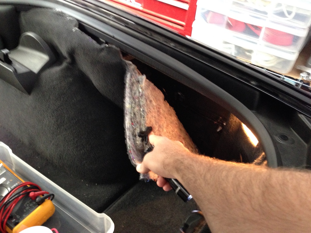
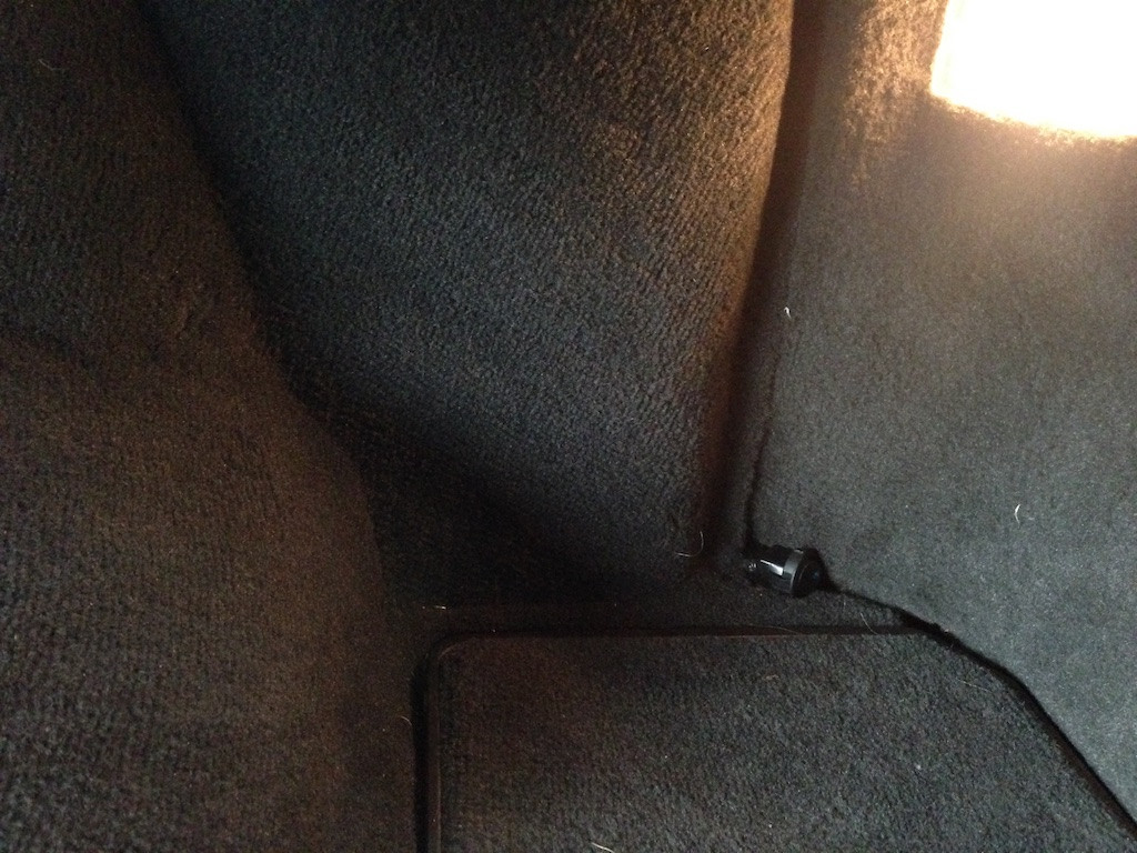
The exhaust module is located over the passenger side rear wheel well. It can easily be accessed by simply pulling back the carpet.
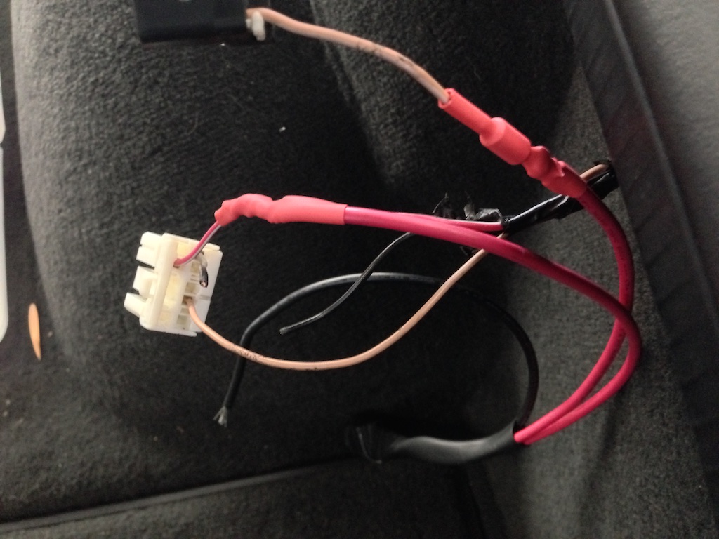
And looks like this:
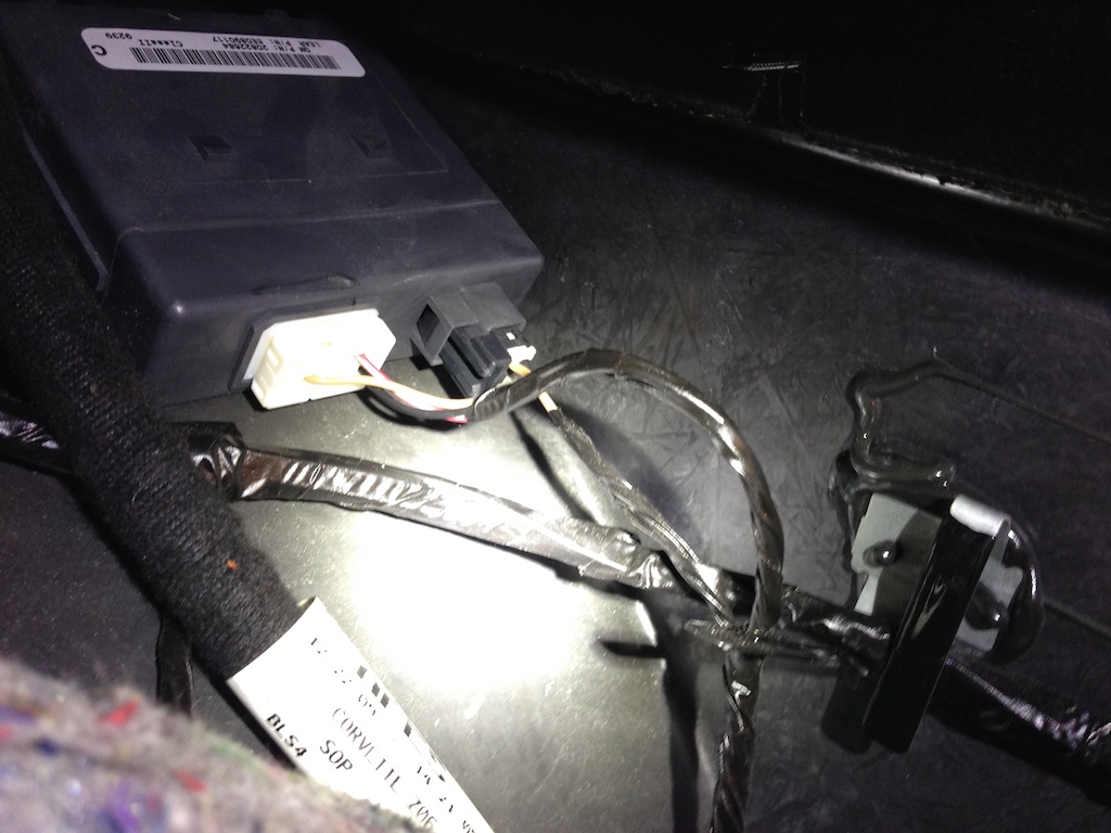
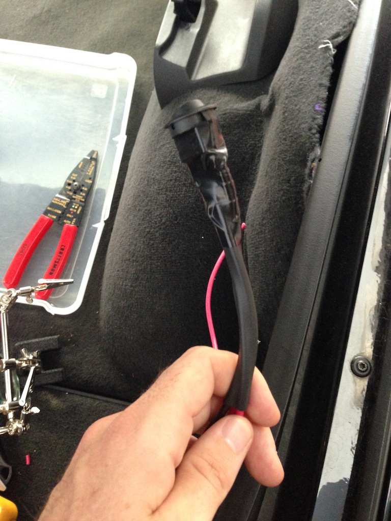
Step 2: Unplug it!
The white plug is power + signal from the Body Control Module, and comes out easily:
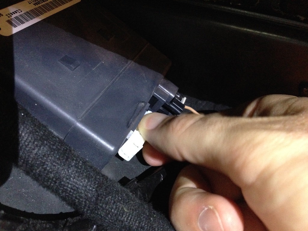
The other plug is the power line to the vacuum solenoid. That one requires a poke tool of your choice (and 2 hands, so no picture) to remove. Use a flashlight for better visibility.
Great success.
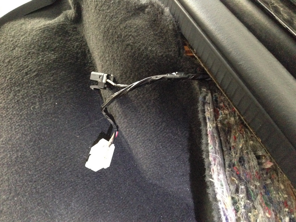
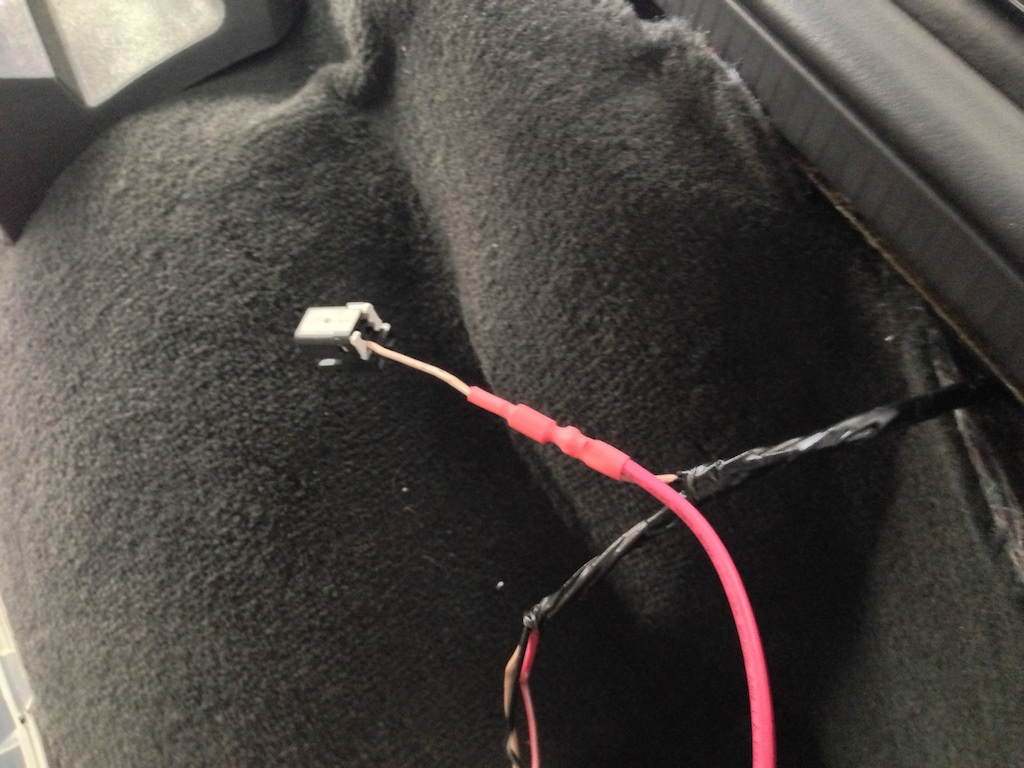
Step 3: Remove the electrical tape
You'll want to strip back a generous amount of the electrical tape from the power / signal lines. They're not very long and splicing them will be easier if you have more room to work.
You can remove most of the electrical tape from the vacuum solenoid wire as well, but this one is a lot easier to work with since its just one wire.
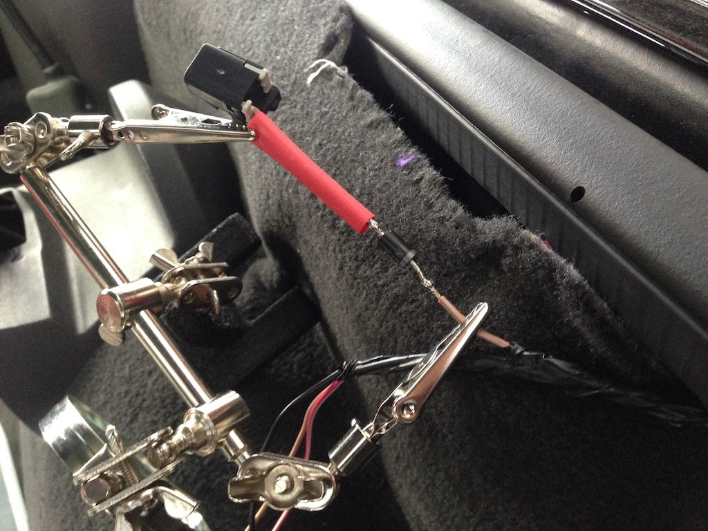
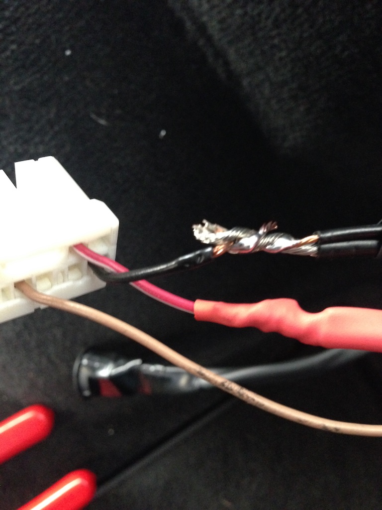
Step 4: Install the diode
Cut the vacuum solenoid line about midway between the connector and harness, then attach the diode with a method of your choosing.
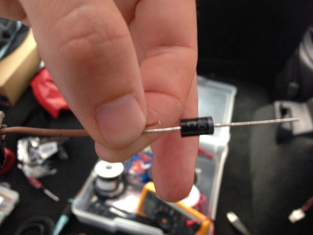
If you have a multimeter, now is a great time to ensure you installed the diode correctly by verifying that you have continuity across the diode. Attach the red lead of the multimeter to the connector end of the diode, and the black lead to the harness side. If you hear a beep you're good to go, if not you probably installed it backwards.
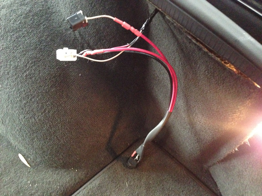
Next install a new power wire (red in the picture) that will feed 12V power from your switch to the vacuum solenoid.
For extra credit, solder and shrink tube the diode and splice wire in place. Otherwise electrical tape will be just fine.
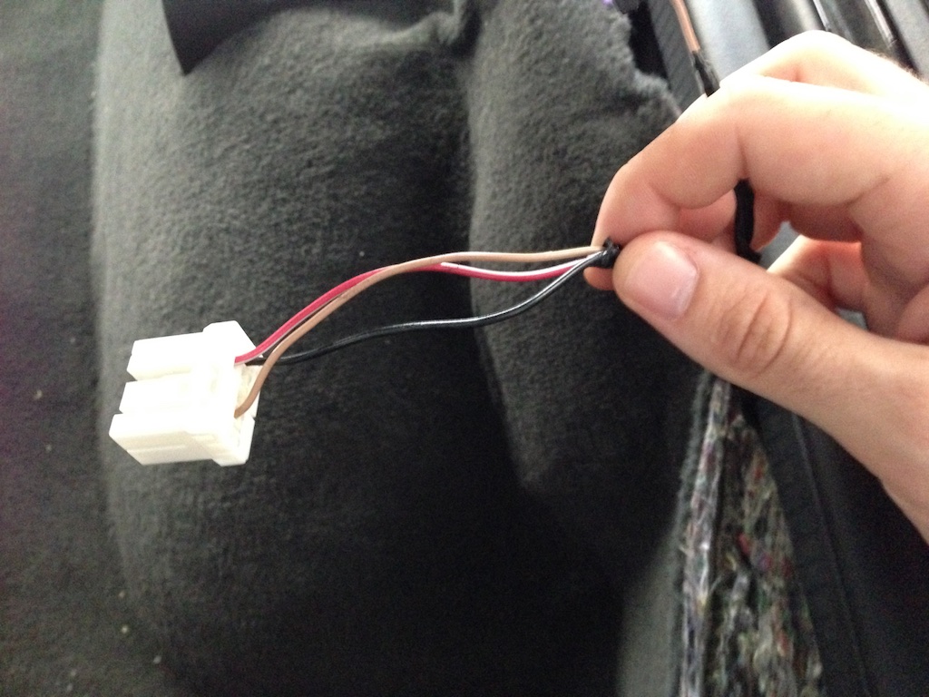
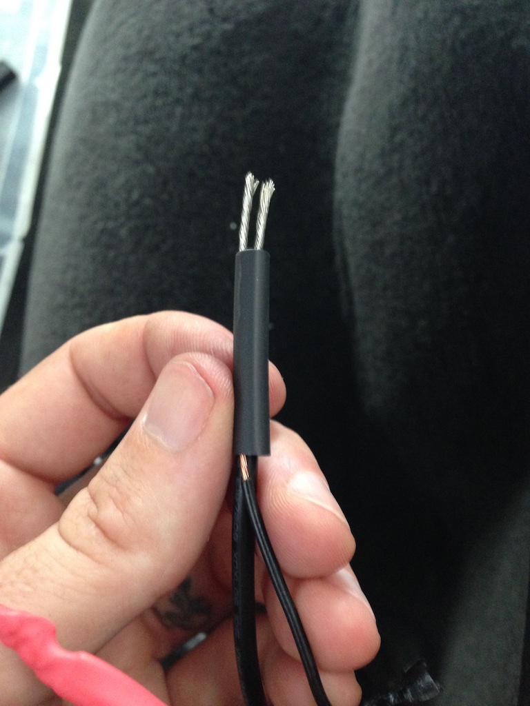
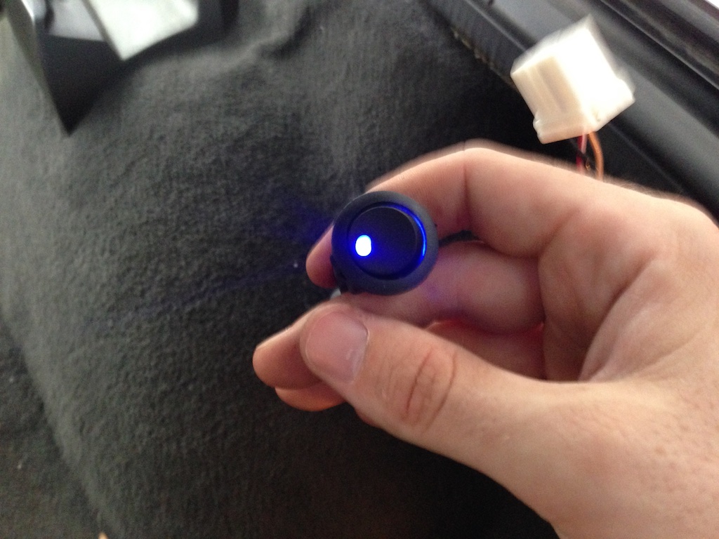
Step 5: Wire up the Switch
Attach (solder, crimp, spit / bubblegum) some wires to your switch:
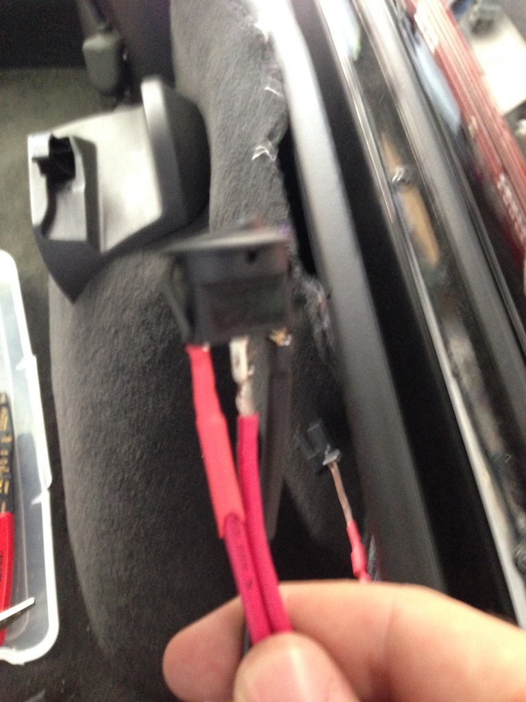
Step 6: Splice the switch in to the ECM harness
Feed 12V power to your switch via the Red / White wire on the ECM harness. Then splice the 12V switched line from your switch in to the vacuum solenoid wire.
If you're using shrink wrap, you'll need to feed the harness side of the wires (ground in the picture) next to the ground line from your switch. Then attach to the connector side with solder or a crimp.
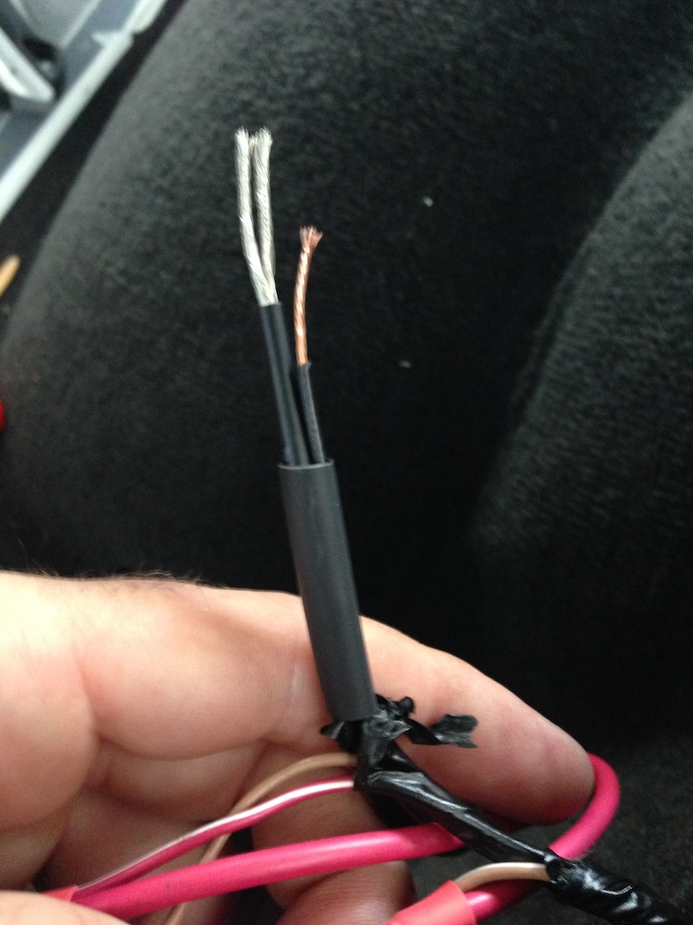
Step 7: Test!
Reconnect the positive battery cable and test your switch (before plugging in to the ECM).
Step 8: Manual Mode
Now plug everything back in to the ECM.
Your engine probably still has a little vacuum from the last time it ran. So if all went well you should be able to flip the switch and hear the valves shut, like in this video:
https://vimeo.com/101816949
If they don't shut, but the switch has power, start up the car to build a bit of vacuum and try again.
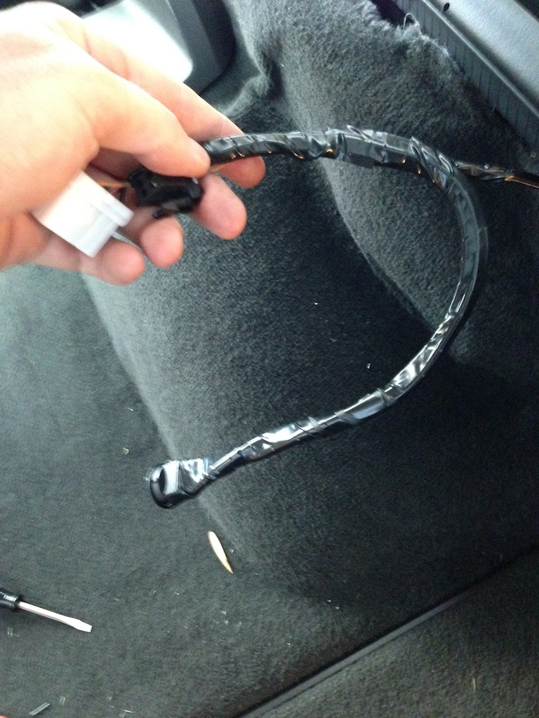
If all is well, tape everything up and replace the carpet.
The limit is so low now (90db) that cars with factory exhaust regularly get pulled. In my case I blew 92.3db during my sound check at full tilt, of course I can lift out of turn 5 and skate by but thats annoying.
A fellow GS owner (thanks Richard!) back in march showed me a switch he uses to force the NPP flaps shut full time, which prevents him from getting ding'd for sound. As there's no DIY for this yet I thought I would write one.
Here's what we're going to build:
And here are the tools you need to do it (plus a bunch of extra stuff):
Tools, the detailed list:
- Wire (I used 14awg because I had it lying around, 20awg would be plenty)
- A diode (I used one of )
- A switch (I used one of )
- Wire cutters / strippers
- Knife / Scissors
- Electrical tape
- 10mm socket to remove the battery cable
- Flashlight
- Poke tool of your choice, I used a small screwdriver
There are also some optional "fancy" tools you can bring if you have them:
- Heat gun
- Heat Shrink Tube (Like )
- Wire crimping tools / crimps
- Soldering iron / solder
- Multimeter
Background:
We use a diode here to prevent the BCM / ECM from getting cranky that we're powering the solenoids when they don't want us to. It doesn't trigger a light but it may log a fault code that a mechanic may misinterperet as a problem with your exhaust.
The ECM connector is always hot, that is to say it recieves B+ power directly from the battery (via the BCM) and in this configuration you'll have to remember to turn the switch off when not on track. I'm ok with this, but a better solution would be to use the power seat / seat heater fuse in the passenger compartment for a 12V supply that is switched to the ignition.
Step 1: Find and unplug the exhaust valve control module
First, disconnect the positive battery cable. Otherwise you'll blow a fuse when you try to splice the ECM connector (its a 10 amp marked ECM . Ask me how I know...
The exhaust module is located over the passenger side rear wheel well. It can easily be accessed by simply pulling back the carpet.
And looks like this:
Step 2: Unplug it!
The white plug is power + signal from the Body Control Module, and comes out easily:
The other plug is the power line to the vacuum solenoid. That one requires a poke tool of your choice (and 2 hands, so no picture) to remove. Use a flashlight for better visibility.
Great success.
Step 3: Remove the electrical tape
You'll want to strip back a generous amount of the electrical tape from the power / signal lines. They're not very long and splicing them will be easier if you have more room to work.
You can remove most of the electrical tape from the vacuum solenoid wire as well, but this one is a lot easier to work with since its just one wire.
Step 4: Install the diode
Cut the vacuum solenoid line about midway between the connector and harness, then attach the diode with a method of your choosing.
If you have a multimeter, now is a great time to ensure you installed the diode correctly by verifying that you have continuity across the diode. Attach the red lead of the multimeter to the connector end of the diode, and the black lead to the harness side. If you hear a beep you're good to go, if not you probably installed it backwards.
Next install a new power wire (red in the picture) that will feed 12V power from your switch to the vacuum solenoid.
For extra credit, solder and shrink tube the diode and splice wire in place. Otherwise electrical tape will be just fine.
Step 5: Wire up the Switch
Attach (solder, crimp, spit / bubblegum) some wires to your switch:
Step 6: Splice the switch in to the ECM harness
Feed 12V power to your switch via the Red / White wire on the ECM harness. Then splice the 12V switched line from your switch in to the vacuum solenoid wire.
If you're using shrink wrap, you'll need to feed the harness side of the wires (ground in the picture) next to the ground line from your switch. Then attach to the connector side with solder or a crimp.
Step 7: Test!
Reconnect the positive battery cable and test your switch (before plugging in to the ECM).
Step 8: Manual Mode
Now plug everything back in to the ECM.
Your engine probably still has a little vacuum from the last time it ran. So if all went well you should be able to flip the switch and hear the valves shut, like in this video:
https://vimeo.com/101816949
If they don't shut, but the switch has power, start up the car to build a bit of vacuum and try again.
If all is well, tape everything up and replace the carpet.

The following users liked this post:
smitty2919 (08-31-2023)
07-27-2014, 01:02 AM
#2
Safety Car


I give you an A for effort on this. This looks like a good permanent solution. I did it a little differently... I just pulled one of the plugs from the control box and made a jumper between two of the wires. In this configuration the exhaust is always powered closed. I just put the jumper in for track days.
07-27-2014, 03:19 PM
#3
Burning Brakes


Never thought of having the exhaust closed all the time. Good write up. Pictures are a little fuzzy but can still see what your doing. I always try to take pictures of the mods I do......seems to never work out. I always get caught up in the project and forget to take pictures.
 07-27-2014, 05:28 PM
#5
Intermediate
Thread Starter
I give you an A for effort on this. This looks like a good permanent solution. I did it a little differently... I just pulled one of the plugs from the control box and made a jumper between two of the wires. In this configuration the exhaust is always powered closed. I just put the jumper in for track days.

I was going to jumper it as well, but eventually I'll probably end up putting this in the center console somewhere with a switched 12v line.
It turns out its also a great mod for getting home late and not waking the wife.
Pictures are a little fuzzy but can still see what your doing.
08-29-2023, 01:03 AM
#6

Not sure if anyone is still monitoring this thread, but would wiring switch in between a one-sided connection to the NPP fuse (bypassing the hot (right) side of the fuse) and a power source (e.g., add a fuse off of heat seater fuse) serve the same purpose?