
LSx oil windage & starvation
 06-15-2009, 06:37 PM
#1
Racer

Thread Starter


Two weeks ago I lent my blown shortblock (det killed #7) to Kevin at crank-scrapers.com. Given the high oil temperatures, low pressures (aeration?) and starvation issues experienced by LSx motors, I'd hoped a crank scraper would help extend the life of my new engine.
Yesterday he tells me his scraper and modified windage tray design is complete. He says:
Of course I have no idea how accurate his statements are; I'm wondering if anyone here has experience running scrapers and trays like this in road racing motors? I'm betting this sort of scraper and tray are nothing new to SBCs.
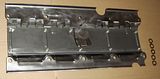
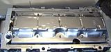
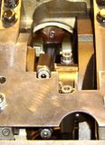
Pics he sent me:
Yesterday he tells me his scraper and modified windage tray design is complete. He says:
Originally Posted by Kevin Johnson
I will modify existing GM windage trays -- there are at least three variations that I have seen. The one in the pictures is the full length one and the F-body one is a 3/4 one. I do not see the point in making completely new trays when the stock ones are excellent platforms to begin with. Here is a description of what was done:
The tray shown is GM part number 12558189 which is the full length one. I also have the shorter F-body one here which will be very similar.
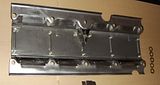
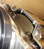
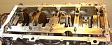
The principal aims were to introduce a small amount of additional order to the windage flow and to extract more entrained oil from the cloud. A divider was used in the center to encourage the flow pattern to circulate in bays 1-2 and 3-4 rather than simply have chaotic flow over the third main. The louvers were extended inward on the downstroke side and then had this element transition into directional screening on the floor. This screening rises above the lowest louver on the opposite side of the tray. This transforms the lowest louver openings into drains (additional drain holes drilled as well). However, because of the orientation of the screening openings (iterated small louvers) the total amount of "louvered" area is greatly increased. The screening helps prevent oil from bouncing back up after striking the interior tray surface and protects oil that has passed through it and is then flowing out of the tray.
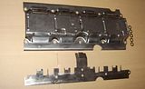
The uppermost upstroke louvers have been opened up a bit and the scraper serves as a new and far closer edge to guide stripped oil into those openings and also to reach in and disrupt the pressure differential of the windage cloud. The scraper moves the windage tray approximately 1.5mm closer to the floor of the pan.
Overall, this is an enhancement of the original design going beyond what is possible with a single stamped piece of metal.
It is thought that the destruction of these engines at high G's is mostly due to oil migrating into the rotating assembly and being trapped by the windage tray and the network of passages through and over the mains/webbing. It becomes churned full of air before being ejected and this increased aeration is what kills the bearings. The scraper and modified tray helps to more quickly extract this oil while still allowing pumping exchanges between cylinders and bays.
The scraper and tray can be used independently of one another if desired. Stroker and Teflon bladed versions of the scraper are available.
The tray shown is GM part number 12558189 which is the full length one. I also have the shorter F-body one here which will be very similar.
The principal aims were to introduce a small amount of additional order to the windage flow and to extract more entrained oil from the cloud. A divider was used in the center to encourage the flow pattern to circulate in bays 1-2 and 3-4 rather than simply have chaotic flow over the third main. The louvers were extended inward on the downstroke side and then had this element transition into directional screening on the floor. This screening rises above the lowest louver on the opposite side of the tray. This transforms the lowest louver openings into drains (additional drain holes drilled as well). However, because of the orientation of the screening openings (iterated small louvers) the total amount of "louvered" area is greatly increased. The screening helps prevent oil from bouncing back up after striking the interior tray surface and protects oil that has passed through it and is then flowing out of the tray.
The uppermost upstroke louvers have been opened up a bit and the scraper serves as a new and far closer edge to guide stripped oil into those openings and also to reach in and disrupt the pressure differential of the windage cloud. The scraper moves the windage tray approximately 1.5mm closer to the floor of the pan.
Overall, this is an enhancement of the original design going beyond what is possible with a single stamped piece of metal.
It is thought that the destruction of these engines at high G's is mostly due to oil migrating into the rotating assembly and being trapped by the windage tray and the network of passages through and over the mains/webbing. It becomes churned full of air before being ejected and this increased aeration is what kills the bearings. The scraper and modified tray helps to more quickly extract this oil while still allowing pumping exchanges between cylinders and bays.
The scraper and tray can be used independently of one another if desired. Stroker and Teflon bladed versions of the scraper are available.
Pics he sent me:


Last edited by GrantB; 06-15-2009 at 06:45 PM.
 06-15-2009, 06:49 PM
#2
Former Vendor
We have been playing with different trays with good results. The scraper looks pretty cool. Is it just the way I read his explaination or is he trying to get rid of oil around #3 main???
Randy
Randy
06-15-2009, 07:54 PM
#3
Le Mans Master


Originally Posted by Kevin Johnson
A divider was used in the center to encourage the flow pattern
to circulate in bays 1-2 and 3-4 rather than simply have chaotic
flow over the third main.
to circulate in bays 1-2 and 3-4 rather than simply have chaotic
flow over the third main.
rid of oil around #3 main?
.

differentiate/isolate the forward bays 1-2 from the rearward bays
3-4. Not so as to "get rid of oil around #3 main", but rather to
reduce migration fore/aft across the location of #3 main as oil
piles up against the side of the tray.
.
06-15-2009, 08:01 PM
#4
Former Vendor
differentiate/isolate the forward bays 1-2 from the rearward bays
3-4. Not so as to "get rid of oil around #3 main", but rather to
reduce migration fore/aft across the location of #3 main as oil
piles up against the side of the tray.
.
Randy
06-18-2009, 09:53 PM
#5
Advanced
Member Since: Sep 2003
Location: Elmira NY
Posts: 71
Likes: 0
Received 0 Likes
on
0 Posts

That's what the oil pump is for! As long as you have the right thrust clearance the thrust should be happy with 40+ psi pumping too it!
Good deal on those scrapers... can't wait to see the teflon versions.
Good deal on those scrapers... can't wait to see the teflon versions.


 06-22-2009, 01:11 AM
#9
Racer
Thread Starter
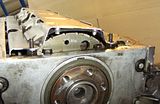
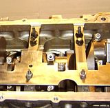
I got the plastic template in for my Katech 427 (Callies crank). It fits over the windage tray studs, and the idea is that you trim the material off the template to fit the motor, then he makes a scraper to fit the template. My template's clearance seems to be perfect on the counterweights, but is pretty far off on the rods.
Now I just need to find a stock crank bolt so I can turn the motor over...
Well some engines don't have pressurized thrust bearings... Do LSx motors?
Now I just need to find a stock crank bolt so I can turn the motor over...
Well some engines don't have pressurized thrust bearings... Do LSx motors?
10-19-2009, 02:25 AM
#10

I got the plastic template in for my Katech 427 (Callies crank). It fits over the windage tray studs, and the idea is that you trim the material off the template to fit the motor, then he makes a scraper to fit the template. My template's clearance seems to be perfect on the counterweights, but is pretty far off on the rods.
Now I just need to find a stock crank bolt so I can turn the motor over...
Now I just need to find a stock crank bolt so I can turn the motor over...


 10-19-2009, 03:22 AM
#11
differentiate/isolate the forward bays 1-2 from the rearward bays
3-4. Not so as to "get rid of oil around #3 main", but rather to
reduce migration fore/aft across the location of #3 main as oil
piles up against the side of the tray.
.
Yes, if you look at the witness marks in a well used windage tray they indicate that entrained oil is flowing along with pumped air back and forth and all around.
There is a reasoning process here -- ceteris paribus the bays should have roughly equivalent oil witness marks from the ejection patterns of the rods and mains given that roughly the same amount of oil is being ejected in each bay. They do not yet we know that a lot of oil is flying around. This means the flow of entrained oil is chaotic.
Secondly, the presence of the tray illustrates that this flow pattern can persist in fairly confined volumes. Moreover the presence of witness marks indicate this is a normal running condition for the stock engine at normal rpms.
Thirdly, we know that GM spent a lot of time developing this isolating tray in order to stop engine failures from lateral (and negative) G loads. It works until the migration and collection of oil under sustained G loads allow neat oil to flood it whereupon the oil is churned full of air. People forget about this earlier GM research when they think that pressure variation in dry sump output is a function strictly of pump stage imbalance or acceleration effects in the sump holding tank. This research came after the Malik patent expressing some of these ideas.
Fourthly, we know that the louvers (a form of scraper technology) in the stock stamped steel pan are insufficient to disrupt this chaotic flow and allow oil to be extracted. Pumping exchange of gases is still allowed -- a good thing but it needs more control.
Fifthly, we know minimally that OEM companies based in Michigan have similar accounting cost reviews of what parts should be included for a given vehicle. The Ford GT had a dry sump system with a complex windage tray -- I do not make this stuff up as I go along, folks. This is why in another thread I was indicating that windage control PRIOR to the scavenge pump _might_ be a good idea and and example of treating causes not effects. Ford seems to agree with that. GM does too but you have to reason it out. The dry sumped Ford GT retailed for roughly $30k to $40k more than the current dry sumped Corvette. You didn't see a dual pump SRT10 engine in the Viper (like in the old BMW M3 Euro S50 or US S54). It was proposed by engineering but rejected by accounting.
This weekend a customer sent a nicely developed gasket with windage tray and integrated scraper in it from a 1996 2.4 Turbo engine from a Mexican market Cirrus. It was also used on the NA 1995 US versions. P/N 4663508A. It is more expensive to make so it was dropped in lieu of a simple gasket which cost the same for the customer. In 2003 the scraper portion of the gasket design was retrieved for use in the SRT4, P/N 04777994AE. Pennies count -- don't ever make the huge mistake that the simple absence of a class of part in an OEM engine means that that part did not do something useful.
10-19-2009, 11:12 PM
#12
Vetteless

Member Since: Jul 2004
Location: Gallatin TN
Posts: 732
Likes: 0
Received 0 Likes
on
0 Posts
St. Jude Donor '09
Wow - some great info in this thread guys, thanks for sharing the knowledge.
I dynamically modified a windage tray at VIR last year by running a few connecting rods and piston shrapnel into, around, and through it at around 6900RPM. The only thing that was clear to me afterwards, besides the fact that racing is an offensively expensive hobby, was that something kinda in the middle of the bottom end let go, but I didn't (and still don't) have the understanding to investigate further. This sheds at least a little light on the situation - I've heard many times that LSX motors tend to starve the bottom end in the middle cylinders - now I can see some evidence as to why.
I dynamically modified a windage tray at VIR last year by running a few connecting rods and piston shrapnel into, around, and through it at around 6900RPM. The only thing that was clear to me afterwards, besides the fact that racing is an offensively expensive hobby, was that something kinda in the middle of the bottom end let go, but I didn't (and still don't) have the understanding to investigate further. This sheds at least a little light on the situation - I've heard many times that LSX motors tend to starve the bottom end in the middle cylinders - now I can see some evidence as to why.
10-22-2009, 10:28 AM
#13
Look at the oil circuit for the Gen III engines (5-563 under Lubrication Flow Schematic). It is a loop feeding the lifters with drops down to the mains. The thrust bearing is located on the center main.
Entrained air bubbles in a dynamic system will react to pressure like a balloon in a closed car. When you accelerate the balloon does not fall to the back window -- it shoots to the front.
In the loop, with pressurized neat(er) oil at either end, just think about being in a car accelerating in opposite directions at the same time. The "balloon" would be then trapped in the center of the car -- right over the feed to the thrust bearing. Et Voila! The thrust bearing and associated main receive a disproportionate amount of air entrained oil leading to failure.
One can predict that the lifters in this and the other side of the loop in the center would also be receiving higher proportions of air. This might encourage combustion events that would exacerbate the degraded oil film in the center.
I don't design engine blocks or heads. I hope this information is useful to GM or aftermarket manufacturers.
 01-15-2010, 11:03 PM
#15
Safety Car

 01-17-2010, 03:56 AM
#16
 01-17-2010, 03:59 AM
#17