
C4 Frame and suspension CAD files
 01-10-2008, 04:06 PM
#21
Melting Slicks

Two different results regarding front camber under braking. Who is correct?
I say the front suspension design is strong and isnt worth any attention. The rear is the weak link, but I dont think any changes will yield much.
I say the front suspension design is strong and isnt worth any attention. The rear is the weak link, but I dont think any changes will yield much.
 01-10-2008, 05:24 PM
#22
Drifting

Brain …. your posts are starting to jog memories.
I started to believe (back then) that the side view drawing wasn’t the final production suspension design, but rather a kind of engineering “neutral” drawing.
Shown with NO Anti-Dive or Anti-Squat built in.
If I were the engineer asked to design this, I would start there to.
Some reasons:
The Anti Dive & Squat angles are about same (9.7 and 10.2 deg, probably both 10 deg – with my scaling errors), that hints to me that it was laid out using the CG, and the CG would then be about 17 inches.
If the CG were any higher (say 18 inches) the Anti-Dive IC (shown) would be below the neutral “AntiDive” line, which (I think) would push the nose down, not up, under braking. The CG would have to be lower (like 16 inches) to resist nose dive under braking, which seams to low to me?
If you compare the measured Anti-Squat angle of 6.3 deg (from my 88) to 9.7 deg, that would give me an Anti-Squat of about 65%, which is close number shown in spec books.
Reversed the other way, if the real Anti-Squat angle was 9.7 deg (from the drawing), to get 62% Anti-Squat, the CG angle would have to be 15.6 deg and the CG height 27 inches, which doesn’t make sense.


Anyway, I’m an engine …. not a suspension guy, and I’ve probably got something backwards here.
Hopefully you’ll figure this all out for the rest of us.
I started to believe (back then) that the side view drawing wasn’t the final production suspension design, but rather a kind of engineering “neutral” drawing.
Shown with NO Anti-Dive or Anti-Squat built in.
If I were the engineer asked to design this, I would start there to.
Some reasons:
The Anti Dive & Squat angles are about same (9.7 and 10.2 deg, probably both 10 deg – with my scaling errors), that hints to me that it was laid out using the CG, and the CG would then be about 17 inches.
If the CG were any higher (say 18 inches) the Anti-Dive IC (shown) would be below the neutral “AntiDive” line, which (I think) would push the nose down, not up, under braking. The CG would have to be lower (like 16 inches) to resist nose dive under braking, which seams to low to me?
If you compare the measured Anti-Squat angle of 6.3 deg (from my 88) to 9.7 deg, that would give me an Anti-Squat of about 65%, which is close number shown in spec books.
Reversed the other way, if the real Anti-Squat angle was 9.7 deg (from the drawing), to get 62% Anti-Squat, the CG angle would have to be 15.6 deg and the CG height 27 inches, which doesn’t make sense.
Anyway, I’m an engine …. not a suspension guy, and I’ve probably got something backwards here.
Hopefully you’ll figure this all out for the rest of us.
Last edited by SuperL98; 01-10-2008 at 05:33 PM.
01-11-2009, 11:07 PM
#23
1st Gear


Member Since: Dec 2008
Posts: 1
Likes: 0
Received 0 Likes
on
0 Posts
Hey Guys,
I'm just playing around with Susp Analyzer and Im working on putting a C4 setup in my '54 chevy car with a 3 link/PHB in the back.
From what I've read and looking at the clip I have, the UCA angles were upward towards the engine and it had a Positive Camber gain until they flattened out and went over center. My rough measurement was +.32. I thought maybe I could improve that since I dont really have any limitations of where I can put things, Im using a turbo'd inline 6 and the car is fairly wide so I have lots of room. Front wheels are 17x9.5 with 7" BS with 275/40 tires.
Im no engineer, but Im trying to learn, and maybe im completely wrong here...
Anyhow heres the screen shots of my modified setup:
Sitting static

1" dive

2" dive

2 deg roll

Thanks for looking.
I'm just playing around with Susp Analyzer and Im working on putting a C4 setup in my '54 chevy car with a 3 link/PHB in the back.
From what I've read and looking at the clip I have, the UCA angles were upward towards the engine and it had a Positive Camber gain until they flattened out and went over center. My rough measurement was +.32. I thought maybe I could improve that since I dont really have any limitations of where I can put things, Im using a turbo'd inline 6 and the car is fairly wide so I have lots of room. Front wheels are 17x9.5 with 7" BS with 275/40 tires.
Im no engineer, but Im trying to learn, and maybe im completely wrong here...
Anyhow heres the screen shots of my modified setup:
Sitting static
1" dive
2" dive
2 deg roll
Thanks for looking.
01-12-2009, 12:42 PM
#24
Team Owner

Thread Starter
Member Since: Mar 2001
Location: Boston, Dallas, Detroit, SoCal, back to Boston MA
Posts: 30,596
Received 238 Likes
on
166 Posts

Coastal thanks for giving this thread a bump, here's my input from the other thread to bring this one up to date:
Looks like the upper arms actually do slope up, which is a a good thing, I was looking at the monoballs to correct that.
Regarding your graphs, I'm surprised the lower arms come up that much.
Are they mounted at the same height as on a Vette?
If not, when you raise it up all the geometries get kinda funny.
That's the trouble with the C4 rear is that the lower link isn't level, but the upper, the half-shaft isn't.
The biggest thing with independant front and solid rear is the roll axis connecting the two ends.
If they'll clear my wheels, looks like a great way to raise my upper control arms
http://www.circletrack.com/techartic.../photo_03.html

Like the tip
I know where I can get metric and regular GM versions, but I'm also fabbing fully adjustable a-arms.
http://www.guldstrand.com/scripts/pr...?idproduct=181

I own my own seat of SolidWorks. So I modelled the mono-ball balljoint yesterday.
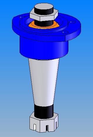
CAD model is coming along.
For now, I'm not actually replacing the bottom one, just the top. It was easy to do a copy/paste and change the dimensions.
I got the upright modeled today, which means I can start playing with it.
All I can say right now, it's that it's rather enlightening to say the least!
http://www.circletrack.com/techartic.../photo_03.html
Like the tip
I know where I can get metric and regular GM versions, but I'm also fabbing fully adjustable a-arms.
http://www.guldstrand.com/scripts/pr...?idproduct=181
I own my own seat of SolidWorks. So I modelled the mono-ball balljoint yesterday.
CAD model is coming along.
For now, I'm not actually replacing the bottom one, just the top. It was easy to do a copy/paste and change the dimensions.
I got the upright modeled today, which means I can start playing with it.
All I can say right now, it's that it's rather enlightening to say the least!
Looks like the upper arms actually do slope up, which is a a good thing, I was looking at the monoballs to correct that.
Regarding your graphs, I'm surprised the lower arms come up that much.
Are they mounted at the same height as on a Vette?
If not, when you raise it up all the geometries get kinda funny.
That's the trouble with the C4 rear is that the lower link isn't level, but the upper, the half-shaft isn't.
The biggest thing with independant front and solid rear is the roll axis connecting the two ends.
01-13-2009, 08:22 PM
#25
Team Owner
Thread Starter
Member Since: Mar 2001
Location: Boston, Dallas, Detroit, SoCal, back to Boston MA
Posts: 30,596
Received 238 Likes
on
166 Posts
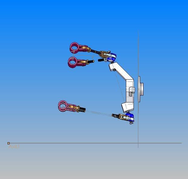
If you recheck the photo, you'll see I added the ground.
Tire circle looks below the surface since it gets squished by the weight of the car.
In order to compensate the lower control arm is no longer level. very similar to the rear.
I'm looking forward to doing the rear and seeing how they match.
right now I'm modelling wheels, stocker, plus the ones I have.
15x7x17 215
16x8.5x32 255
16x8.5x50 255
16x9.5x38 255
16x9.5x56 255
17x8.5x56 255
17x9.5x56 275/285
17x11x36 315 ZR1
17x11x50 315 GS
Need to measure my offsets
17x12
18x12
01-13-2009, 08:54 PM
#26
Le Mans Master

Brian, have you looked into Howe Racing ball joints? IMO they are better than monoballs as they have more angularity and they are an enclosed ball joint. They have various length studs that you can easily change to correct geometry. They are very high quality pieces.
http://www.howeracing.com/Suspension...ints-Upper.htm

http://www.howeracing.com/Suspension...ints-Upper.htm
01-17-2009, 10:48 AM
#28
Team Owner
Member Since: Apr 2001
Location: Overwhelmed as one would be, placed in my position.... DFW, TX
Posts: 36,451
Likes: 0
Received 2 Likes
on
2 Posts
St. Jude Donor '05

BC-
What is your end goal from this? I'm really hoping to improve the handling of my C4 which, as it turns out, is not exactly the fastest thing on the track. Who knew?
What is your end goal from this? I'm really hoping to improve the handling of my C4 which, as it turns out, is not exactly the fastest thing on the track. Who knew?
01-17-2009, 12:35 PM
#29
Team Owner
Thread Starter
Member Since: Mar 2001
Location: Boston, Dallas, Detroit, SoCal, back to Boston MA
Posts: 30,596
Received 238 Likes
on
166 Posts
Same here, just seeing what can be done w/o reinventing it.
I'm going to have adjustable links front and rear, right not I just want to see what small changes to those make. I'll be able to change rear caster, which you can't do on the stock setup.
I'm going to have adjustable links front and rear, right not I just want to see what small changes to those make. I'll be able to change rear caster, which you can't do on the stock setup.
01-17-2009, 03:22 PM
#30
Team Owner
Member Since: Apr 2001
Location: Overwhelmed as one would be, placed in my position.... DFW, TX
Posts: 36,451
Likes: 0
Received 2 Likes
on
2 Posts
St. Jude Donor '05
[QUOTE=BrianCunningham;1568586564]Same here, just seeing what can be done w/o reinventing it.
I'm going to have adjustable links front and rear, right not I just want to see what small changes to those make. I'll be able to change rear caster, parts for that?
http://www.vbandp.com/detail.aspx?ID=530
I'm going to have adjustable links front and rear, right not I just want to see what small changes to those make. I'll be able to change rear caster, parts for that?
http://www.vbandp.com/detail.aspx?ID=530
Last edited by Umrswimr; 01-17-2009 at 03:57 PM.
01-17-2009, 04:32 PM
#31
Team Owner
Thread Starter
Member Since: Mar 2001
Location: Boston, Dallas, Detroit, SoCal, back to Boston MA
Posts: 30,596
Received 238 Likes
on
166 Posts
Yup
I bought some similar ones from astock.
I also got the camber links.
The model will also give me the spring rate/a-arm movement ratio I need for my new coilover setup.
I bought some similar ones from astock.
I also got the camber links.
The model will also give me the spring rate/a-arm movement ratio I need for my new coilover setup.
02-01-2009, 08:49 PM
#32
Team Owner
Thread Starter
Member Since: Mar 2001
Location: Boston, Dallas, Detroit, SoCal, back to Boston MA
Posts: 30,596
Received 238 Likes
on
166 Posts
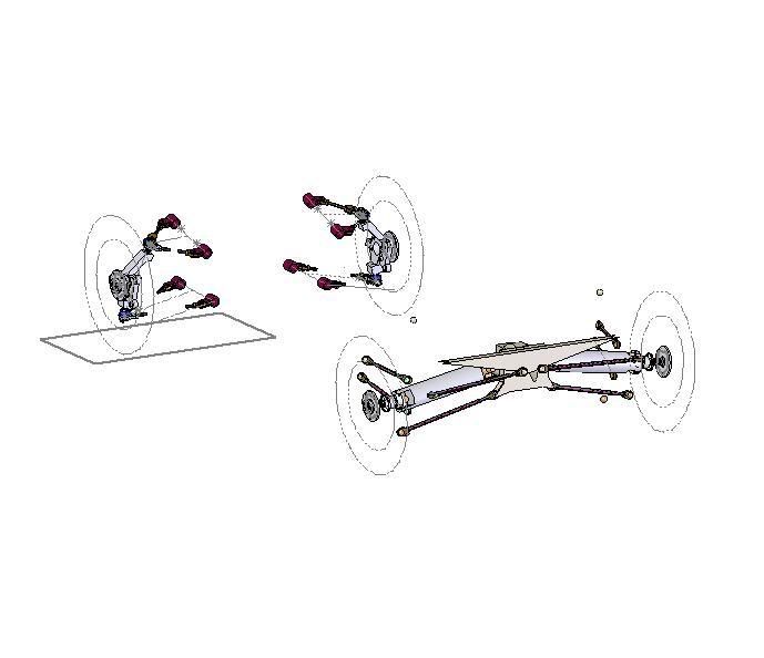
More progress.
I got all the rear links in, I'm going to have to make more measurements.
A difference of a few millimeters can shift it from toe-in to toe-out, from positive to negative camber
I got all the rear links in, I'm going to have to make more measurements.
A difference of a few millimeters can shift it from toe-in to toe-out, from positive to negative camber