DIY stealth C6 coupe audio upgrade [pics]
 07-14-2011, 08:24 AM
#1
Drifting

Thread Starter
Member Since: Jun 2006
Location: Chicago Illinois
Posts: 1,294
Likes: 0
Received 17 Likes
on
16 Posts
St. Jude Donor '12

I have successfully upgraded the audio system in my C6 coupe after reading, studying, and learning from the members of this forum. The audio upgrade is a time-consuming, but a very rewarding project. Don’t be discouraged by the learning curve. To the uninitiated, the audio install could be a daunting task. To the brave, the rewards will be plentiful.
Warning: there is a strong chance that installing an aftermarket audio system may result in voiding portions of one’s warranty, broken clips, busted knuckles, cut fingers and plenty of epithets. The audio upgrade may result in short-circuiting electrical components or even fire. I expressly disclaim any and all responsibility for any damage and/or loss that results from information that is relied upon, either in whole or in part, from this thread and reliance upon information contained herein constitutes acceptance of the disclaimer. Proceed at your own risk.
Because my vette is a daily driver, the install was completed in phases so that I could tackle the project on weekends. My goal was to significantly upgrade the audio system for a reasonable price while maintaining a stealth and discreet system. For now, I am retaining the stock navigation head unit. For the purpose of this write-up I assume that you will be removing the panels from the doors, removing the center console, and capable of removing other trim parts.
Phase 1: install deadening in doors, speakers, amp
The first phase can be completed in one weekend, but it will require tearing deep into the vette. Your goal will be to complete this portion of the install without turning your car in a shiny and expensive brick. Before connecting or removing any of the car’s electrical connections, disconnect the negative battery terminal from the battery post. Just loosen the cam nut, no need to remove it completely, but if you lose a cam nut then you can find it online for $5 at the major online auction website.
What you will need:
amp(s)
bracket to install amp(s)
speakers
speaker baffles
speaker wire (nobody will tell you how much you need, but you should buy more than you think)
crimp connectors for speaker terminals
crimp bullet connectors for tweeter wire
crimp spade terminals for amp and crossovers
two grommets with inner diameter large enough for your wire
18 gauge 12 volt power turn on lead
4 gauge power wire
4 gauge ground wire
ring terminal for ground wire
ring terminal for power wire
inline fuse holder and fuse
batter post terminal
8 gauge power and ground wire from distribution blocks to amps (not needed for one amp)
fused power distribution block w/ fuses (not needed for one amp)
ground distribution block (not needed for one amp)
modified PAC GM ADD-24 (remember to use female RCA plugs)
interconnects (3 feet is sufficient if amps are in foot well)
right angle RCA plug adapters
antenna isolator with adapters
aluminum channels
door plate (and screws)
BXTII
Ensolite
silicone adhesive
3M dual lock velcro (at least two packages)
zip ties
electrical tape
deadening in doors
You should strongly consider installing sound deadener and vibration dampener on and in the doors after you remove the door panels. Following Rick at RAAMaudio’s advice, I also installed an aluminum channel in the door to increase the door’s stiffness. The aluminum channels are adhered to the door with double-sided tape and are approximately four inches apart and have BXTII between the channels, which is rolled up the side of the channels. You will want to line the outer door skin with BXTII. You will also want to install an 8” x 8” square of Ensolite behind the speaker opening. Don't overdo it with the Ensolite inside the door or you will lose your low end. There is also a vinyl vapor barrier that should be replaced with something stiffer. You can either fabricate your own plate or buy an alumilite panel from Rick at RAAMaudio. I covored the panel in Ensolite, fit it against the door, drilled pilot holes, and screwed in stainless steel screws to hold it in place.
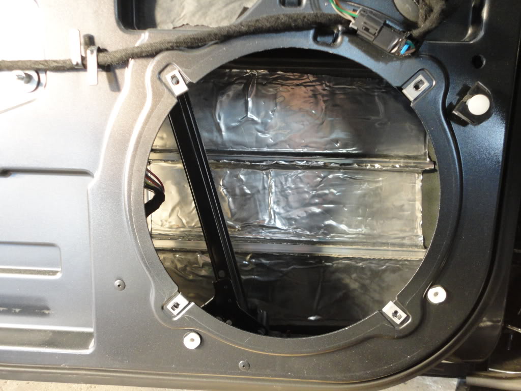
Pic of the driver’s side door with the aluminum channels and BXTII
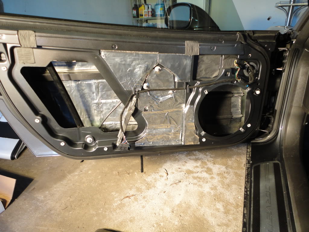
Pic of the door with BXTII installed as well as a square piece of ensolite behind the speaker opening.
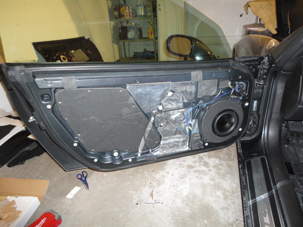
Pic of the final door with the Ensolite -covered panel screwed in and the speaker installed into a speaker baffle that has been covered in Ensolite. You will see 16 gauge speaker wire run through the factory grommet with bullet connectors for the tweeters. You will also see the alumillite covered in Ensolite. On the driver's side the angled piece of metal that is used to attach the door panel had to be removed.
Take your time properly stiffening up the doors and deadening them in order to turn your doors into better speaker boxes.
speakers
For speakers, I chose Polk Audio mm6501 component speakers. They come with 6.5” mid-range drivers and 1” tweeters and a crossover. The components are rated at 125 watts RMS with a peak of 250 watts and a nominal impedance of 2.7 ohms. These are good affordably-priced speakers. The components are mounted to speaker baffles manufactures and sold by nakidparts. I had to enlarge the opening on the tweeter speaker baffle to two inches in order to flush mount the tweeters. The speaker baffles are also available from Rick at RAAMaudio. It is commonly suggested to disconnect the center channel speaker and the rear speakers. Removing the stock amplifier as described in this post will effectively eliminate the center and rear speakers.
Tip: spray paint your speaker baffles flat black, or better yet, wrap them in Ensolite. Also, the install location in each door for the tweeter speaker baffles is not symmetrical. The little notch is up on one door and down on the other. Take a close look when you remove the door panels.
If you are running component speakers, many here would suggest that you not install the crossovers in the doors due to moisture and shock. I installed mine using 3M dual lock Velcro in a cavity that is located directly above the passenger foot well area towards the fender. When running wire to the doors you will need to pop off a rectangular panel that is found above each foot well near the fenders. This panel already has a wire harness that runs through it, but you should be able to pull it away far enough away to drill a hole. Install grommet and then run speaker wire through.
DSC01073.jpg?t=1310615813
Pic taken straight up showing both crossovers mounted opposite one another above passenger foot well. Also visible is the panel used to run speaker wire to doors.
I ran 14 gauge Stinger speaker wire from the amp to the crossover, then 14 gauge speaker wire from each crossover to the 6.5” speaker and 16 gauge speaker wire from each crossover to the tweeter. I did not bridge the amp for fear of sending too much power to the components. I ran my driver’s side speaker wire behind the console over to the passenger side foot well. It is not tough to fish the wire through the accordion-like grommet in the door jam. Be sure to zip tie the old speaker wire in the door to the wire harness. You should also zip tie the new speaker wire to keep it from interfering with the power window. You will need to run the speaker wire that goes to the tweeter through the door so that it can be connected to the tweeter, which mounts to the door panel. You can either drill a whole through your 6.5” speaker baffle, you can drill a hole in the door, or you can run the speaker wire through the existing grommet. I ran the tweeter’s speaker wire through the factory grommet and dabbed some silicone on the hold that ended up getting punctured. I also clipped the connectors that came with the tweeters and crimped bullet connectors.
All of my speaker connections (at speakers, at amp and at crossovers) are properly crimped using a ratcheting crimper. Highly recommended over a cheapie crimper.
amp
For the amp, I chose Arc Audio ks 125.4 mini (rated at 75 x 4 @ 4 ohms, 125 x 4 @ 2 ohms, 250 x 2 @ 2 ohms bridged) and ks 500.1 mini (rated at 310 x 1 @ 4 ohms, 500 x 1 @ 2 ohms). These amps could be installed in the passenger foot well, but they are a tight fit. The benefit of installing the amps in the foot well includes maintaining a stealth install that does not require a sled or the loss of space in a storage cubby. The downside is the need to stuff a tiny amp into a small space, which makes final tuning more difficult. I have not yet had any overheating problems and the amps have not gone into thermal protection. Both amps are mounted to a custom bracket made by Rick at RAAMaudio. Other options for a stealth install involve placing an amp in one of the rear storage cubbies or behind a passenger seat. An amp will not fit below the seat of a C6. It is reported that the Kenwood XR-5s and Alpine PDX-5 both fit in the rear storage cubbies.
You will need to run power through the firewall. The battery posts for my 2010 C6 coupe use a cam nut, which makes connecting wires directly to the battery posts a little more difficult. Initially, I used the remote positive post located in the fuse box in the engine compartment and used four gauge Stinger wire. At first I tried crimping the ring terminal using the hammer method, which proved somewhat effective, but not very reassuring. I ended up re-crimping using a Harbor Freight hydraulic crimper. Word of caution, the under hood fuse box is powered with a six gauge wire. Since I was not satisfied with the gauge mis-match and the poor connection with the positive battery post and the over-designed battery post terminal, I replaced the battery terminal with a Stinger HPM batter terminal.
About 12-18 inches from the positive power source, I connected a Stinger ANL waterproof fuse holder (60 amp ANL fuse used, but don't insert the fuse until all of your connections have been completed). The fuse holder is attached with 3M dual lock velcro near the battery. You will need to run power wire through the firewall. You can drill a new hole and install a new grommet or you can use the existing grommet. I chose to use the existing grommet. You will see the factory wire harness and grommet after you remove the battery. You will also need to remove the plastic panel above the passenger foot well (remove two push pins with a pry tool and remove the light assembly from the panel). To get the power wire through the firewall, I ran a coat hanger from inside the car to the engine compartment, then taped the power wire to the coat hanger with electrical tape, applied some lubricant to the wire and then did a push-pull to get the wire through the grommet. It is probably easier to get the power wire to go from the passenger compartment to the engine compartment. It would be helpful to have an extra set of hands. Be sure to pull enough power wire through the grommet to be able to route the wire around the battery to your fuse holder. In the passenger cabin, the 4 gauge power wire runs to a Stinger fused distribution block. From here you can run 8 gauge power wire to each amplifier.
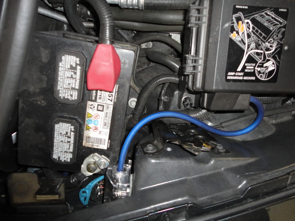
Pic of the power wire running from the remove power location to the inline fuse, which is mounted near the battery with 3m dual lock velcro tape. I later moved the power source from the remote battery location directly to the battery. Pic below.
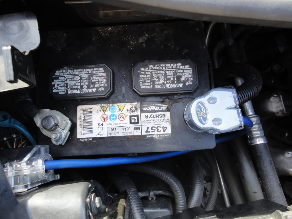
Update: 1.6.12. I relocated the power from the remote location to the positive battery post. The remote power location at the fuse box is fed by a six gauge wire. I thought it would be better to relocate my 4 gauge amp power wire to the positive battery post. I am using a Stinger HPM battery terminal. Very solid connection to the battery terminal.
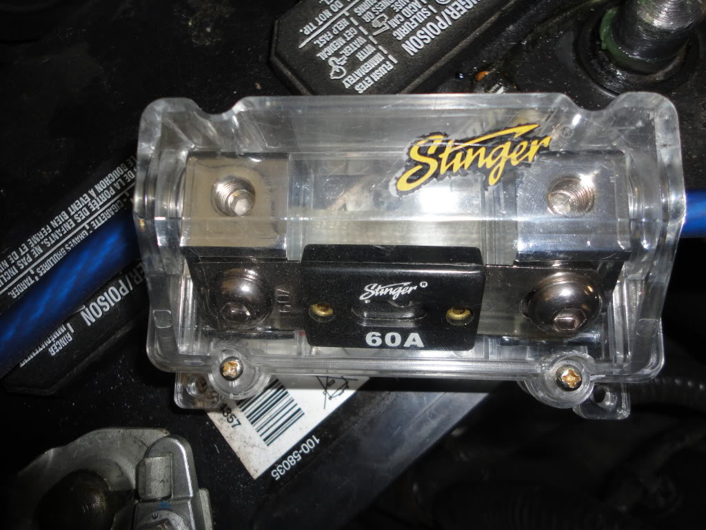
Pic of the Stinger fuse holder with 60 amp fuse.
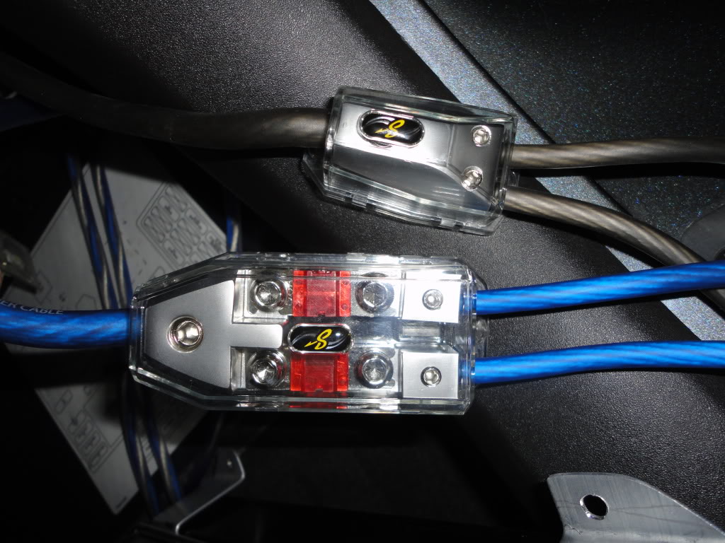
Pic of the Stinger ground distribution block and the Stinger fused distribution block with 50 amp fuses. Each block has 4 gauge wire going in and 8 gauge wire coming out.
One of the most reliable grounds is located on the pillar of the passenger seat. You can gain access to the ground location by pulling up on the plastic molding near the carpet and then pulling the plastic side panel (pull the side panel straight towards the other side of the car). Grind some paint away to get good contact, crimp a ring terminal onto your ground wire and run the ground wire under the carpet and forward. You may be able to ground you amp at one of two bolts located above the passenger foot well, but may be better to stick with a trusted ground location to avoid problems with ground loops.
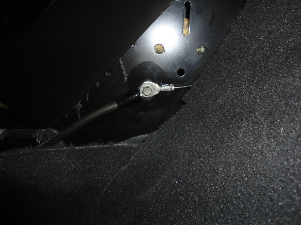
Pic of the ground location
DSC01334.jpg?t=1307678934
Pic of the ground location taken during phase two
Pic of an alternate ground location that worked; however, I ended up changing the ground to the passenger pillar when diagnosing my audio system for noise in the speakers. The two bolts visible in this pic may be usable as grounds if one takes remedial action against undesirable noise in the system (more later). In this photo you will see a Singer interconnect which was connected to a patch cable and my ipod while I diagnosed noise in the system.
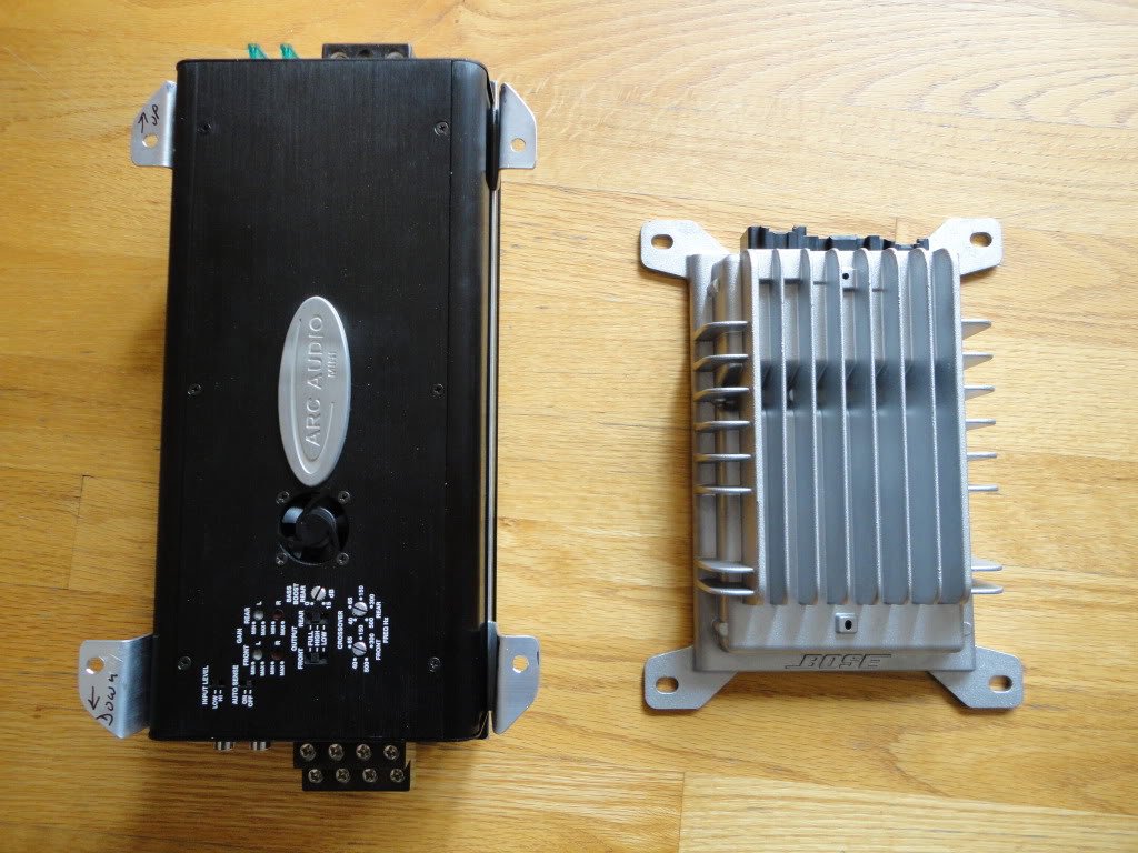
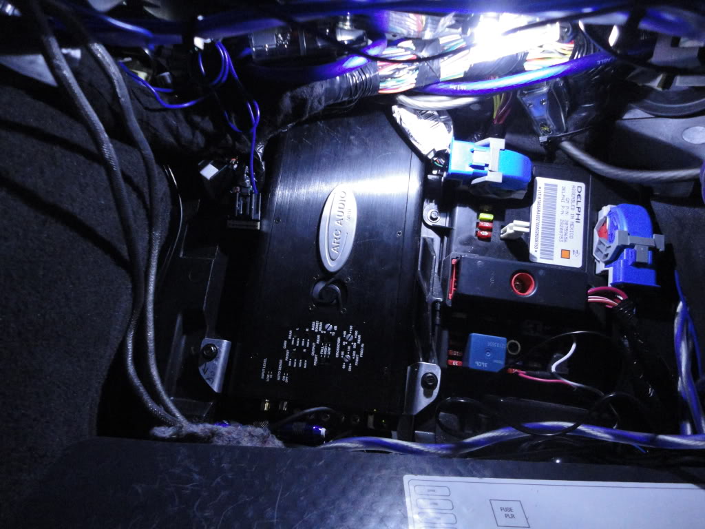
Pic of the Arc Audio amps on custom bracket next to the stock Bose amp.
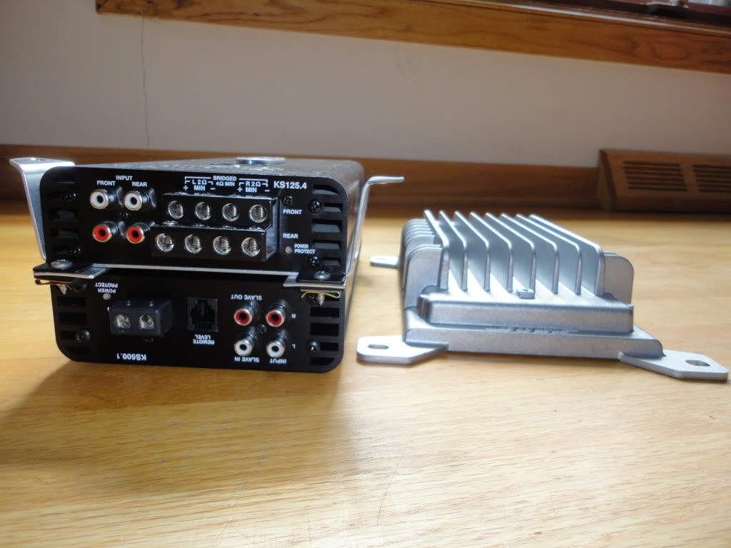
Pic of the Arc Audio amps on custom bracket next to the stock Bose amp.
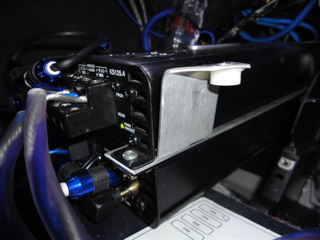
Pic of Arc Audio amps on custom bracket with 1/4" nylon spacers bonded with silicone adhesive (added during phase 3).
You will need to run a 12 volt turn-on lead. You have two choices: 1) you can either use an add-a-fuse circuit installed in the fuse box on the wiper fuse or you can splice into the wiring harness at the stereo connection and splice into wire B3. The drawback of using the connection at B3 is that the amp will turn on whenever you open the door in order to operate the door chimes. The benefit is that after you turn off the car you will continue to have sound during retained accessory power (RAP) until you open the door. There is a way to correct this with a diode as explained by markcz here, but I have not figured out how to wire it up.
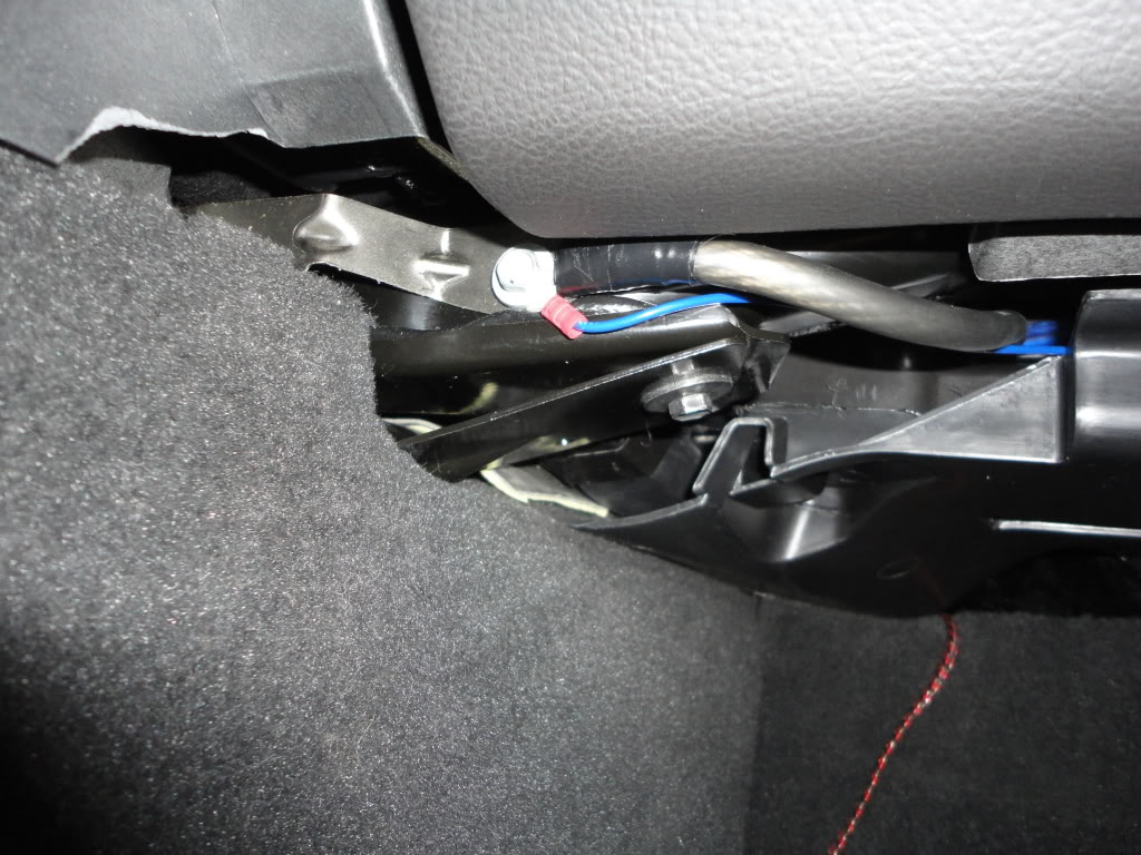
Removing the Bose amp from the foot well is straightforward. It is retained by four screws and has a few plugs that have to be disconnected. Squeezing the Arc Audio amps into the cavity is a little more involved. Don’t install the amps until after you have verified that everything works and until after you have initially tuned the amp that you will not be able to access. In order to fit the amps I had to clip a zip tie or two on the car’s wiring harness, and I had to unplug a large blue connector that goes into the fuse box. You will have to move and push some things around. There was also a card connected to the wiring harness that was clipped to the left wall of the cavity. I had to shuffle this card around and I had to remove the clip to remove the card to make room for the amps.
You will need to run signal from your head unit to the amp. The stock units put out an ok signal (fairly low voltage), which can be sent tot he amp using a modified PAC ADD-GM24 harness. To do this, follow TheKomoman’s instructions: http://forums.corvetteforum.com/audi...r-harness.html
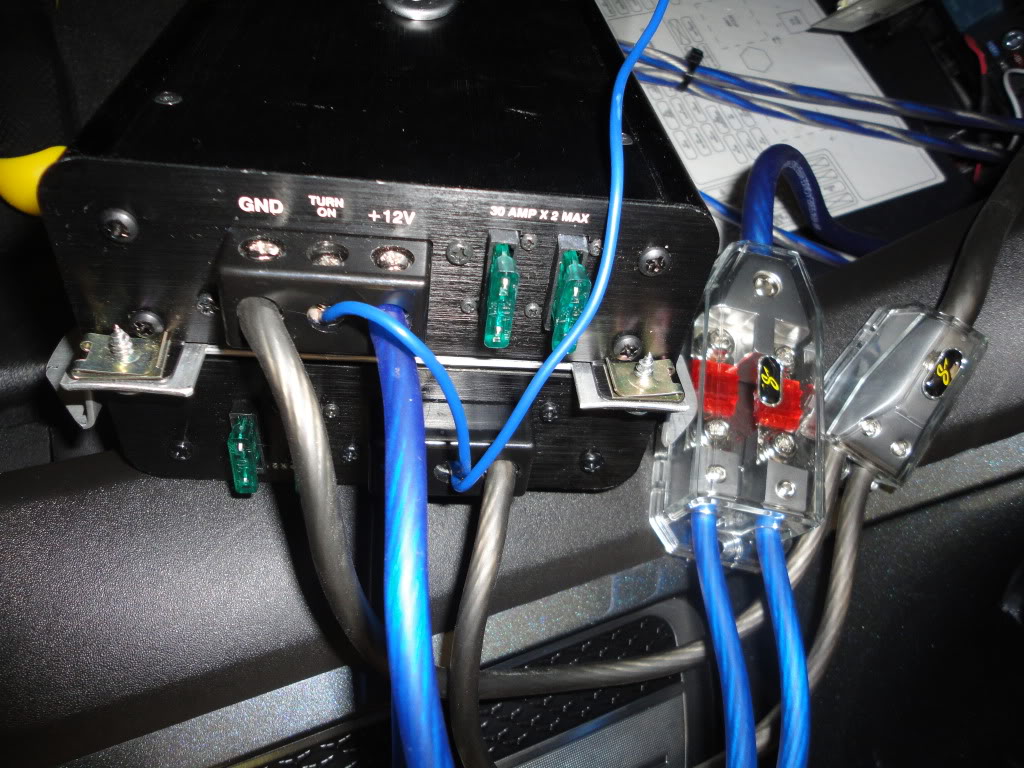
Pic of the power connections to the amps. You will see that the turn-on lead goes to one amp and is jumped to the other with a short wire.
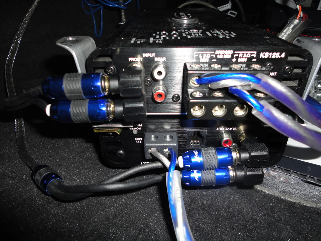
Pic of the speaker input and output connections to the amps.
After your amp has all of its connections (speaker wire, power wire, ground wire, turn on lead, and RCA interconnects), it will be time to test the system before putting everything back together. Install the fuse and connect the battery. Test the system with the engine running and not running. I had horrible noise / whine / squeal in my system. The solution for 95% of the problem (thanks pentavolvo) was to ground the negative side of the RCA interconnects to the head unit’s chassis. Use a small piece of wire, strip a small bit off the end, wedge it against the edge of the male interconnect and attach the interconnect to the female counterpart. It will be a tight fit and you will need to make sure the wire does not touch the positive portion of the male RCA plug.
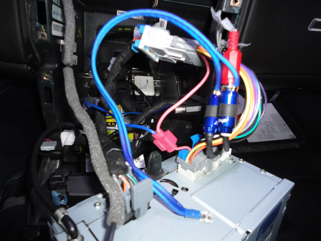
Pic of the negative side of the RCA interconnects grounded to a screw on the head unit.
The remaining 5% of the whine / squeal / noise was eliminated using an antenna isolator. If you notice a high pitch in your speakers that goes away when you unplug the antenna from the head unit, then you need an antenna isolator. The antenna isolator that I purchased from the website named after a South American rain forest is manufactured by DLC (no part number). The antenna isolator that I received had connections for a standard antenna plug; however, GM changed the size of the antenna plug from a standard plug to a mini plug so I had to use metra 40-gm10 and metra 40-gm20 to complete the connection.
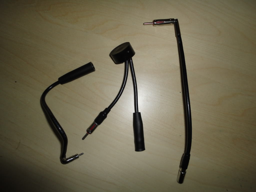
Pic of the antenna isolator. The far left item is metra 40-gm20, the middle item is the DLC antenna isolator, and the right item is metra 40-gm10
DSC01468.jpg?t=1310619970
Pic of antenna isolator plugged into head unit (interconnect ground also visible). You will see a zip tie that I ran though two holes and wrapped around the antenna wire to keep the antenna securely connected (the connection was not tight). In this pic you will also see that both interconnects are grounded to the head unit chassis and crimped to one spade connector.
If you continue to have whine / squeal / noise, then you may need a ground loop isolator / noise filter. I tried three different noise filters with varying success, the best of which was PAC SNI1 Noise Isolator. Thankfully, I am not currently using any ground loop isolators or noise filters on the RCA interconnects.
Once you have verified that everything works then you can put everything back together.
Pic of amps stuffed into the footwell without the plastic trim piece below the glove box.

Pic of the power fused distribution block wedged up into a cavity behind the car's wiring harness. There is a zip tie around the cover to the distribution block to prevent it from vibrating loose (possible overkill).
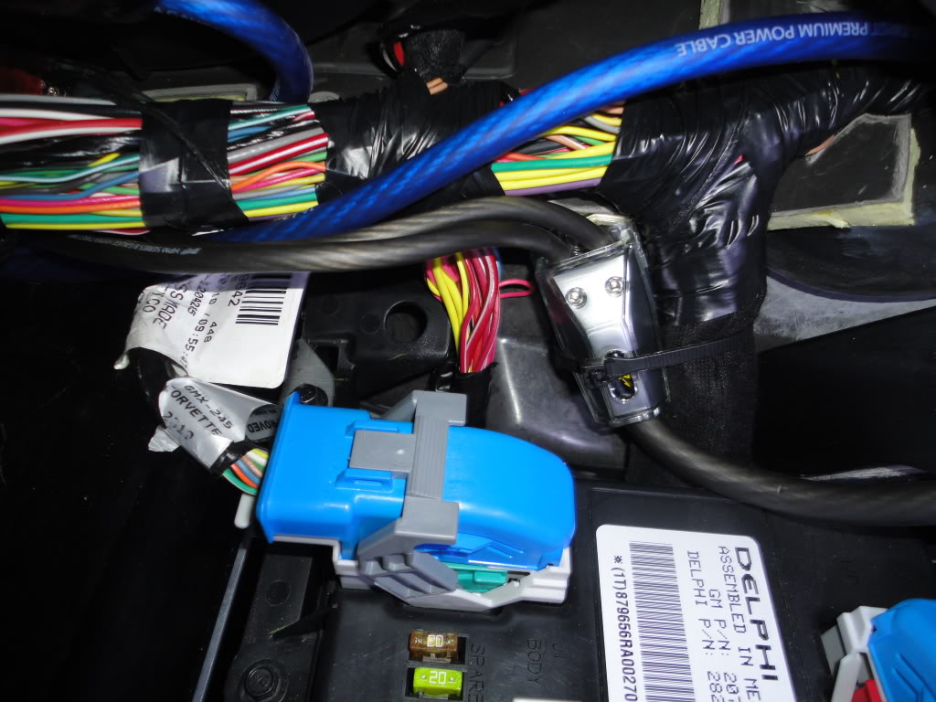
Pic of the ground distribution block which is zip tied some plastic behind the wiring harness. In this pic you will also see a big blue plug, this plug must be disconnected in order to remove and install the amps into the footwell.
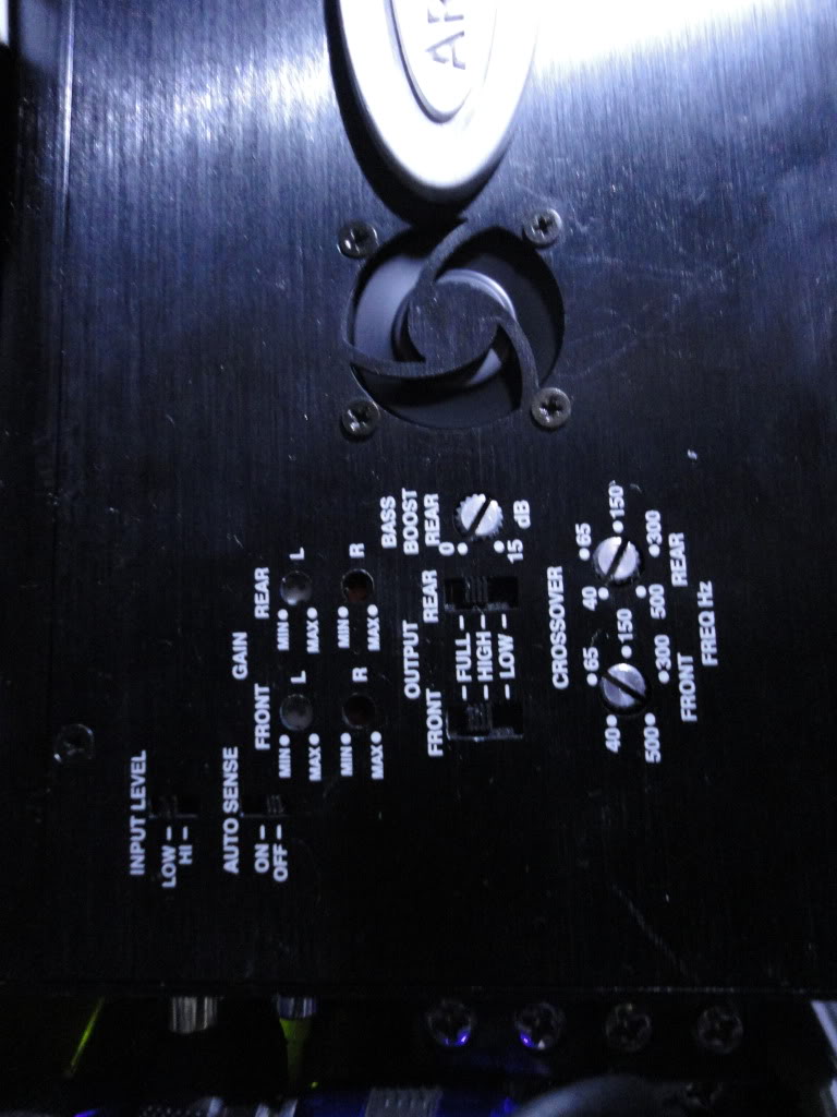
Pic of settings for the Arc Audio 125.4. These settings take into account the installed sub and the crossover is set to high pass at around 70 hz. Without the sub I would set the crossover to full.
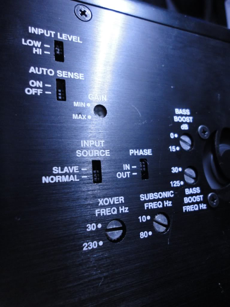
Pic of settings for the Arc Audio 500.1 that I am running with the sub. The settings are as follows:
input level: low
auto sense: off
gain: max
input source: normal
phase: in
bass boost: 0 db
bass boost: not relevant, but dialed to 30 hz
xover freq: 100 hz
subsonic freq: not relevant since free air box, but dialed to 10 hz
DSC01471.jpg?t=1310620202
Pic of Arc Audio amps in passenger foot well next to fuse box.
Phase 2: deadening and insulation throughout the car, wire for sub
what you will need:
BXTII
Ensolite
heat insulation
silver tape
I installed sound deadener (BXTII), vibration dampener (ensolite) and heat insulation (Madvette kit) in an effort to reduce road noise, to decrease panel vibration, and decrease interior heat. Gutting the car, installing everything, and then reassembling everything is a big project that will consume a weekend. I will defer instruction on how to disassemble the interior to the tutorials provided by the manufacturers of heat insulation, but I will offer a few tips.
The four push pins that hold the rear speaker panels to the panel below the halo break easily. Pry them out a bit and then try to grab them with needle nose plyers. Also, when you remove the rear speaker panel by pulling it loose from the clips, don’t rotate the panel or else you risk cracking off a white post that contains a clip (easily reattached with epoxy). Pull this panel straight towards the other side of the car. The grill in the rear speaker panel is loose, so use silicone adhesive on each tab to prevent the grill from vibrating.
DSC01339.jpg?t=1310619307
Pic of inside of rear speaker panel with silicone on the metal tabs.
DSC01309.jpg?t=1310619421
Pic of gutted hatch.
DSC01311.jpg?t=1310619464
Pic of gutted interior.
DSC01312.jpg?t=1310619497
Pic of trunk floor and wheel wells covered in BXTII.
DSC01314.jpg?t=1310619579
Pic of interior covered in BXTII.
DSC01317.jpg?t=1310619623
Pic of trunk floor and wheel wells covered in Ensolite.
DSC01320.jpg?t=1310619688
Pic of interior covered in Ensolite.
DSC01328.jpg?t=1310619730
Pic of trunk floor and wheel wells covered in heat insulation.
DSC01330.jpg?t=1310619785
Pic of interior covered in heat insulation.
DSC01329.jpg?t=1310619810
Another pic of interior covered in heat insulation.
Phase 3: install subwoofer
What you will need:
Sub Box
Subwoofer
speaker wire
During phase two, I ran 14 gauge speaker wire from the passenger foot well under the carpet by the passenger door, to the back of the hatch, across the hatch and then down to the driver’s side storage cubby.
DSC01333.jpg?t=1310619861
Pic of speaker wire running over rear passenger wheel well zip tied / taped off to keep secure.
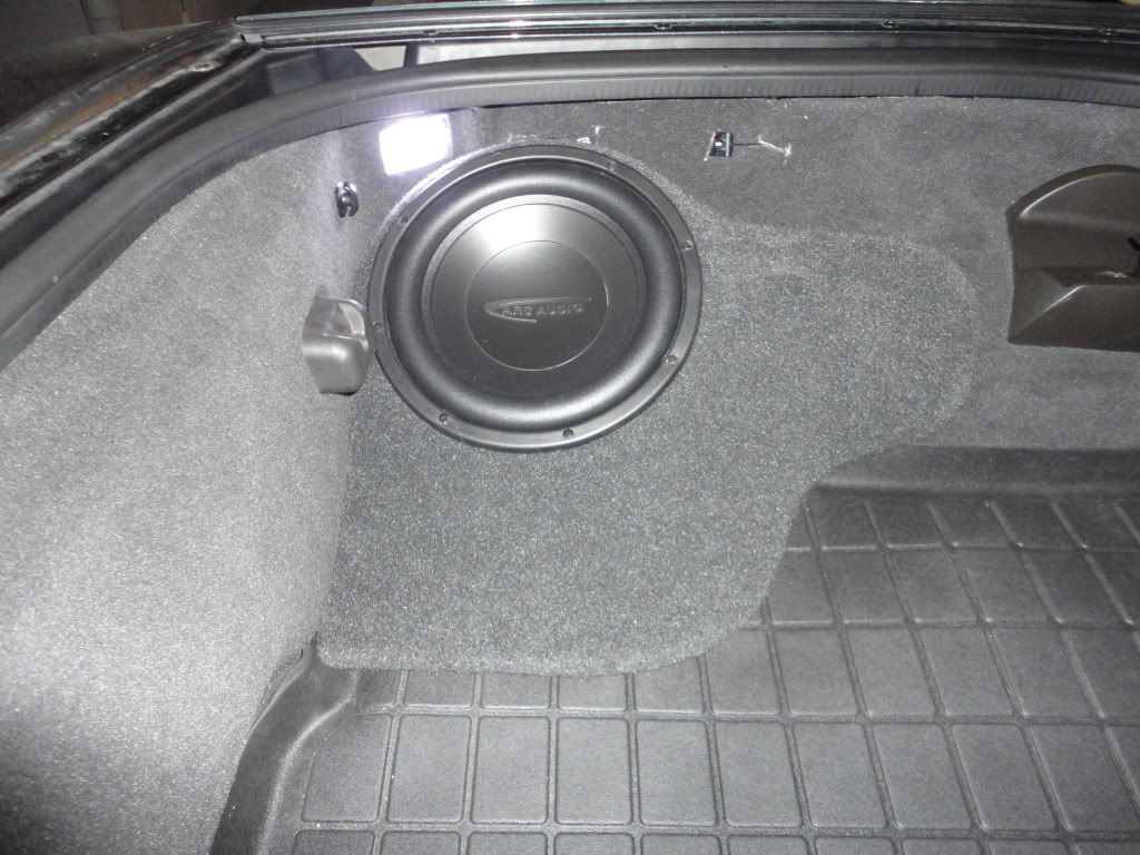
Pic of RAAMaudio sub box and Arc Audio 10 D4 sub wired in parallel. When the dual voice coils are wired in parallel (positive to positive and negative to negative) the amp sees a 2 ohm load. The weathertech cargo mat was cut to accommodate the sub box.
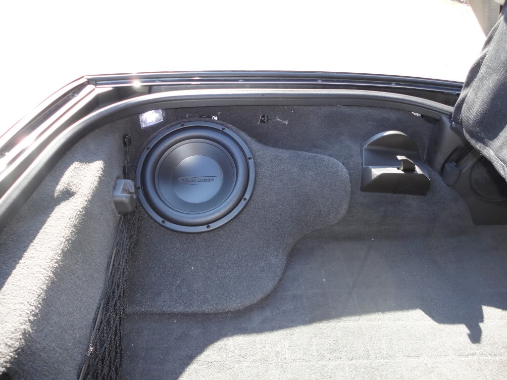
Another pic of the sub and sub box without the weathertech cargo mat.
Phase 4: endless tweaking
I added Polk Audio mm521 5.25" coaxial speakers in the rear. It would have been much easier to install these speakers when all of the interior was removed for the insulation install. I ran 14 gauge speaker wire from the amp along the passenger side by the door tucked under the carpet (removed the manual door release to get the wire deeper into the carpet). To get the speaker wire to the driver's side, I ran the speaker wire under the cargo carpet. These speakers have a small crossover, which I adhered using 3m dual lock velcro to each wheel well. There is plenty of space for the crossover in the cavity behind each rear speaker. The speaker wire was crimp-connected to the crossover with a butt connector. I used an RCA y-splitter to split the front signal in order to provide signal to the rear channels on the amp. My sub gets its signal from the rear signal. The benefit of this setup is that I can adjust the subwoofer using the fade adjustment on the head unit. The downside is that the front and rear speakers cannot be adjusted independently by the head unit and must be adjusted on the amp. The gain is set to the lowest setting for the rear speakers. Sorry, no pictures. The sound is more robust with the addition of the rear speakers.
I would like to thank the contributors to the audio section of the corvetteforum for their insight during my efforts to upgrade the audio system. The project was a major time commitment, but the results are worthwhile. I can now hear music at highway speeds without the targa top. I hope the details contained in this post help other members. So far, I am very pleased with the results.
For more help in upgrading the audio system in your vette, read the threads that are posted in the FAQ and read other members' install threads. Thrash has a very detailed and informative thread HERE
Warning: there is a strong chance that installing an aftermarket audio system may result in voiding portions of one’s warranty, broken clips, busted knuckles, cut fingers and plenty of epithets. The audio upgrade may result in short-circuiting electrical components or even fire. I expressly disclaim any and all responsibility for any damage and/or loss that results from information that is relied upon, either in whole or in part, from this thread and reliance upon information contained herein constitutes acceptance of the disclaimer. Proceed at your own risk.
Because my vette is a daily driver, the install was completed in phases so that I could tackle the project on weekends. My goal was to significantly upgrade the audio system for a reasonable price while maintaining a stealth and discreet system. For now, I am retaining the stock navigation head unit. For the purpose of this write-up I assume that you will be removing the panels from the doors, removing the center console, and capable of removing other trim parts.
Phase 1: install deadening in doors, speakers, amp
The first phase can be completed in one weekend, but it will require tearing deep into the vette. Your goal will be to complete this portion of the install without turning your car in a shiny and expensive brick. Before connecting or removing any of the car’s electrical connections, disconnect the negative battery terminal from the battery post. Just loosen the cam nut, no need to remove it completely, but if you lose a cam nut then you can find it online for $5 at the major online auction website.
What you will need:
amp(s)
bracket to install amp(s)
speakers
speaker baffles
speaker wire (nobody will tell you how much you need, but you should buy more than you think)
crimp connectors for speaker terminals
crimp bullet connectors for tweeter wire
crimp spade terminals for amp and crossovers
two grommets with inner diameter large enough for your wire
18 gauge 12 volt power turn on lead
4 gauge power wire
4 gauge ground wire
ring terminal for ground wire
ring terminal for power wire
inline fuse holder and fuse
batter post terminal
8 gauge power and ground wire from distribution blocks to amps (not needed for one amp)
fused power distribution block w/ fuses (not needed for one amp)
ground distribution block (not needed for one amp)
modified PAC GM ADD-24 (remember to use female RCA plugs)
interconnects (3 feet is sufficient if amps are in foot well)
right angle RCA plug adapters
antenna isolator with adapters
aluminum channels
door plate (and screws)
BXTII
Ensolite
silicone adhesive
3M dual lock velcro (at least two packages)
zip ties
electrical tape
deadening in doors
You should strongly consider installing sound deadener and vibration dampener on and in the doors after you remove the door panels. Following Rick at RAAMaudio’s advice, I also installed an aluminum channel in the door to increase the door’s stiffness. The aluminum channels are adhered to the door with double-sided tape and are approximately four inches apart and have BXTII between the channels, which is rolled up the side of the channels. You will want to line the outer door skin with BXTII. You will also want to install an 8” x 8” square of Ensolite behind the speaker opening. Don't overdo it with the Ensolite inside the door or you will lose your low end. There is also a vinyl vapor barrier that should be replaced with something stiffer. You can either fabricate your own plate or buy an alumilite panel from Rick at RAAMaudio. I covored the panel in Ensolite, fit it against the door, drilled pilot holes, and screwed in stainless steel screws to hold it in place.
Pic of the driver’s side door with the aluminum channels and BXTII
Pic of the door with BXTII installed as well as a square piece of ensolite behind the speaker opening.
Pic of the final door with the Ensolite -covered panel screwed in and the speaker installed into a speaker baffle that has been covered in Ensolite. You will see 16 gauge speaker wire run through the factory grommet with bullet connectors for the tweeters. You will also see the alumillite covered in Ensolite. On the driver's side the angled piece of metal that is used to attach the door panel had to be removed.
Take your time properly stiffening up the doors and deadening them in order to turn your doors into better speaker boxes.
speakers
For speakers, I chose Polk Audio mm6501 component speakers. They come with 6.5” mid-range drivers and 1” tweeters and a crossover. The components are rated at 125 watts RMS with a peak of 250 watts and a nominal impedance of 2.7 ohms. These are good affordably-priced speakers. The components are mounted to speaker baffles manufactures and sold by nakidparts. I had to enlarge the opening on the tweeter speaker baffle to two inches in order to flush mount the tweeters. The speaker baffles are also available from Rick at RAAMaudio. It is commonly suggested to disconnect the center channel speaker and the rear speakers. Removing the stock amplifier as described in this post will effectively eliminate the center and rear speakers.
Tip: spray paint your speaker baffles flat black, or better yet, wrap them in Ensolite. Also, the install location in each door for the tweeter speaker baffles is not symmetrical. The little notch is up on one door and down on the other. Take a close look when you remove the door panels.
If you are running component speakers, many here would suggest that you not install the crossovers in the doors due to moisture and shock. I installed mine using 3M dual lock Velcro in a cavity that is located directly above the passenger foot well area towards the fender. When running wire to the doors you will need to pop off a rectangular panel that is found above each foot well near the fenders. This panel already has a wire harness that runs through it, but you should be able to pull it away far enough away to drill a hole. Install grommet and then run speaker wire through.
DSC01073.jpg?t=1310615813
Pic taken straight up showing both crossovers mounted opposite one another above passenger foot well. Also visible is the panel used to run speaker wire to doors.
I ran 14 gauge Stinger speaker wire from the amp to the crossover, then 14 gauge speaker wire from each crossover to the 6.5” speaker and 16 gauge speaker wire from each crossover to the tweeter. I did not bridge the amp for fear of sending too much power to the components. I ran my driver’s side speaker wire behind the console over to the passenger side foot well. It is not tough to fish the wire through the accordion-like grommet in the door jam. Be sure to zip tie the old speaker wire in the door to the wire harness. You should also zip tie the new speaker wire to keep it from interfering with the power window. You will need to run the speaker wire that goes to the tweeter through the door so that it can be connected to the tweeter, which mounts to the door panel. You can either drill a whole through your 6.5” speaker baffle, you can drill a hole in the door, or you can run the speaker wire through the existing grommet. I ran the tweeter’s speaker wire through the factory grommet and dabbed some silicone on the hold that ended up getting punctured. I also clipped the connectors that came with the tweeters and crimped bullet connectors.
All of my speaker connections (at speakers, at amp and at crossovers) are properly crimped using a ratcheting crimper. Highly recommended over a cheapie crimper.
amp
For the amp, I chose Arc Audio ks 125.4 mini (rated at 75 x 4 @ 4 ohms, 125 x 4 @ 2 ohms, 250 x 2 @ 2 ohms bridged) and ks 500.1 mini (rated at 310 x 1 @ 4 ohms, 500 x 1 @ 2 ohms). These amps could be installed in the passenger foot well, but they are a tight fit. The benefit of installing the amps in the foot well includes maintaining a stealth install that does not require a sled or the loss of space in a storage cubby. The downside is the need to stuff a tiny amp into a small space, which makes final tuning more difficult. I have not yet had any overheating problems and the amps have not gone into thermal protection. Both amps are mounted to a custom bracket made by Rick at RAAMaudio. Other options for a stealth install involve placing an amp in one of the rear storage cubbies or behind a passenger seat. An amp will not fit below the seat of a C6. It is reported that the Kenwood XR-5s and Alpine PDX-5 both fit in the rear storage cubbies.
You will need to run power through the firewall. The battery posts for my 2010 C6 coupe use a cam nut, which makes connecting wires directly to the battery posts a little more difficult. Initially, I used the remote positive post located in the fuse box in the engine compartment and used four gauge Stinger wire. At first I tried crimping the ring terminal using the hammer method, which proved somewhat effective, but not very reassuring. I ended up re-crimping using a Harbor Freight hydraulic crimper. Word of caution, the under hood fuse box is powered with a six gauge wire. Since I was not satisfied with the gauge mis-match and the poor connection with the positive battery post and the over-designed battery post terminal, I replaced the battery terminal with a Stinger HPM batter terminal.
About 12-18 inches from the positive power source, I connected a Stinger ANL waterproof fuse holder (60 amp ANL fuse used, but don't insert the fuse until all of your connections have been completed). The fuse holder is attached with 3M dual lock velcro near the battery. You will need to run power wire through the firewall. You can drill a new hole and install a new grommet or you can use the existing grommet. I chose to use the existing grommet. You will see the factory wire harness and grommet after you remove the battery. You will also need to remove the plastic panel above the passenger foot well (remove two push pins with a pry tool and remove the light assembly from the panel). To get the power wire through the firewall, I ran a coat hanger from inside the car to the engine compartment, then taped the power wire to the coat hanger with electrical tape, applied some lubricant to the wire and then did a push-pull to get the wire through the grommet. It is probably easier to get the power wire to go from the passenger compartment to the engine compartment. It would be helpful to have an extra set of hands. Be sure to pull enough power wire through the grommet to be able to route the wire around the battery to your fuse holder. In the passenger cabin, the 4 gauge power wire runs to a Stinger fused distribution block. From here you can run 8 gauge power wire to each amplifier.
Pic of the power wire running from the remove power location to the inline fuse, which is mounted near the battery with 3m dual lock velcro tape. I later moved the power source from the remote battery location directly to the battery. Pic below.
Update: 1.6.12. I relocated the power from the remote location to the positive battery post. The remote power location at the fuse box is fed by a six gauge wire. I thought it would be better to relocate my 4 gauge amp power wire to the positive battery post. I am using a Stinger HPM battery terminal. Very solid connection to the battery terminal.
Pic of the Stinger fuse holder with 60 amp fuse.
Pic of the Stinger ground distribution block and the Stinger fused distribution block with 50 amp fuses. Each block has 4 gauge wire going in and 8 gauge wire coming out.
One of the most reliable grounds is located on the pillar of the passenger seat. You can gain access to the ground location by pulling up on the plastic molding near the carpet and then pulling the plastic side panel (pull the side panel straight towards the other side of the car). Grind some paint away to get good contact, crimp a ring terminal onto your ground wire and run the ground wire under the carpet and forward. You may be able to ground you amp at one of two bolts located above the passenger foot well, but may be better to stick with a trusted ground location to avoid problems with ground loops.
Pic of the ground location
DSC01334.jpg?t=1307678934
Pic of the ground location taken during phase two
Pic of an alternate ground location that worked; however, I ended up changing the ground to the passenger pillar when diagnosing my audio system for noise in the speakers. The two bolts visible in this pic may be usable as grounds if one takes remedial action against undesirable noise in the system (more later). In this photo you will see a Singer interconnect which was connected to a patch cable and my ipod while I diagnosed noise in the system.
Pic of the Arc Audio amps on custom bracket next to the stock Bose amp.
Pic of the Arc Audio amps on custom bracket next to the stock Bose amp.
Pic of Arc Audio amps on custom bracket with 1/4" nylon spacers bonded with silicone adhesive (added during phase 3).
You will need to run a 12 volt turn-on lead. You have two choices: 1) you can either use an add-a-fuse circuit installed in the fuse box on the wiper fuse or you can splice into the wiring harness at the stereo connection and splice into wire B3. The drawback of using the connection at B3 is that the amp will turn on whenever you open the door in order to operate the door chimes. The benefit is that after you turn off the car you will continue to have sound during retained accessory power (RAP) until you open the door. There is a way to correct this with a diode as explained by markcz here, but I have not figured out how to wire it up.
Removing the Bose amp from the foot well is straightforward. It is retained by four screws and has a few plugs that have to be disconnected. Squeezing the Arc Audio amps into the cavity is a little more involved. Don’t install the amps until after you have verified that everything works and until after you have initially tuned the amp that you will not be able to access. In order to fit the amps I had to clip a zip tie or two on the car’s wiring harness, and I had to unplug a large blue connector that goes into the fuse box. You will have to move and push some things around. There was also a card connected to the wiring harness that was clipped to the left wall of the cavity. I had to shuffle this card around and I had to remove the clip to remove the card to make room for the amps.
You will need to run signal from your head unit to the amp. The stock units put out an ok signal (fairly low voltage), which can be sent tot he amp using a modified PAC ADD-GM24 harness. To do this, follow TheKomoman’s instructions: http://forums.corvetteforum.com/audi...r-harness.html
Pic of the power connections to the amps. You will see that the turn-on lead goes to one amp and is jumped to the other with a short wire.
Pic of the speaker input and output connections to the amps.
After your amp has all of its connections (speaker wire, power wire, ground wire, turn on lead, and RCA interconnects), it will be time to test the system before putting everything back together. Install the fuse and connect the battery. Test the system with the engine running and not running. I had horrible noise / whine / squeal in my system. The solution for 95% of the problem (thanks pentavolvo) was to ground the negative side of the RCA interconnects to the head unit’s chassis. Use a small piece of wire, strip a small bit off the end, wedge it against the edge of the male interconnect and attach the interconnect to the female counterpart. It will be a tight fit and you will need to make sure the wire does not touch the positive portion of the male RCA plug.
Pic of the negative side of the RCA interconnects grounded to a screw on the head unit.
The remaining 5% of the whine / squeal / noise was eliminated using an antenna isolator. If you notice a high pitch in your speakers that goes away when you unplug the antenna from the head unit, then you need an antenna isolator. The antenna isolator that I purchased from the website named after a South American rain forest is manufactured by DLC (no part number). The antenna isolator that I received had connections for a standard antenna plug; however, GM changed the size of the antenna plug from a standard plug to a mini plug so I had to use metra 40-gm10 and metra 40-gm20 to complete the connection.
Pic of the antenna isolator. The far left item is metra 40-gm20, the middle item is the DLC antenna isolator, and the right item is metra 40-gm10
DSC01468.jpg?t=1310619970
Pic of antenna isolator plugged into head unit (interconnect ground also visible). You will see a zip tie that I ran though two holes and wrapped around the antenna wire to keep the antenna securely connected (the connection was not tight). In this pic you will also see that both interconnects are grounded to the head unit chassis and crimped to one spade connector.
If you continue to have whine / squeal / noise, then you may need a ground loop isolator / noise filter. I tried three different noise filters with varying success, the best of which was PAC SNI1 Noise Isolator. Thankfully, I am not currently using any ground loop isolators or noise filters on the RCA interconnects.
Once you have verified that everything works then you can put everything back together.
Pic of amps stuffed into the footwell without the plastic trim piece below the glove box.
Pic of the power fused distribution block wedged up into a cavity behind the car's wiring harness. There is a zip tie around the cover to the distribution block to prevent it from vibrating loose (possible overkill).
Pic of the ground distribution block which is zip tied some plastic behind the wiring harness. In this pic you will also see a big blue plug, this plug must be disconnected in order to remove and install the amps into the footwell.
Pic of settings for the Arc Audio 125.4. These settings take into account the installed sub and the crossover is set to high pass at around 70 hz. Without the sub I would set the crossover to full.
Pic of settings for the Arc Audio 500.1 that I am running with the sub. The settings are as follows:
input level: low
auto sense: off
gain: max
input source: normal
phase: in
bass boost: 0 db
bass boost: not relevant, but dialed to 30 hz
xover freq: 100 hz
subsonic freq: not relevant since free air box, but dialed to 10 hz
DSC01471.jpg?t=1310620202
Pic of Arc Audio amps in passenger foot well next to fuse box.
Phase 2: deadening and insulation throughout the car, wire for sub
what you will need:
BXTII
Ensolite
heat insulation
silver tape
I installed sound deadener (BXTII), vibration dampener (ensolite) and heat insulation (Madvette kit) in an effort to reduce road noise, to decrease panel vibration, and decrease interior heat. Gutting the car, installing everything, and then reassembling everything is a big project that will consume a weekend. I will defer instruction on how to disassemble the interior to the tutorials provided by the manufacturers of heat insulation, but I will offer a few tips.
The four push pins that hold the rear speaker panels to the panel below the halo break easily. Pry them out a bit and then try to grab them with needle nose plyers. Also, when you remove the rear speaker panel by pulling it loose from the clips, don’t rotate the panel or else you risk cracking off a white post that contains a clip (easily reattached with epoxy). Pull this panel straight towards the other side of the car. The grill in the rear speaker panel is loose, so use silicone adhesive on each tab to prevent the grill from vibrating.
DSC01339.jpg?t=1310619307
Pic of inside of rear speaker panel with silicone on the metal tabs.
DSC01309.jpg?t=1310619421
Pic of gutted hatch.
DSC01311.jpg?t=1310619464
Pic of gutted interior.
DSC01312.jpg?t=1310619497
Pic of trunk floor and wheel wells covered in BXTII.
DSC01314.jpg?t=1310619579
Pic of interior covered in BXTII.
DSC01317.jpg?t=1310619623
Pic of trunk floor and wheel wells covered in Ensolite.
DSC01320.jpg?t=1310619688
Pic of interior covered in Ensolite.
DSC01328.jpg?t=1310619730
Pic of trunk floor and wheel wells covered in heat insulation.
DSC01330.jpg?t=1310619785
Pic of interior covered in heat insulation.
DSC01329.jpg?t=1310619810
Another pic of interior covered in heat insulation.
Phase 3: install subwoofer
What you will need:
Sub Box
Subwoofer
speaker wire
During phase two, I ran 14 gauge speaker wire from the passenger foot well under the carpet by the passenger door, to the back of the hatch, across the hatch and then down to the driver’s side storage cubby.
DSC01333.jpg?t=1310619861
Pic of speaker wire running over rear passenger wheel well zip tied / taped off to keep secure.
Pic of RAAMaudio sub box and Arc Audio 10 D4 sub wired in parallel. When the dual voice coils are wired in parallel (positive to positive and negative to negative) the amp sees a 2 ohm load. The weathertech cargo mat was cut to accommodate the sub box.
Another pic of the sub and sub box without the weathertech cargo mat.
Phase 4: endless tweaking
I added Polk Audio mm521 5.25" coaxial speakers in the rear. It would have been much easier to install these speakers when all of the interior was removed for the insulation install. I ran 14 gauge speaker wire from the amp along the passenger side by the door tucked under the carpet (removed the manual door release to get the wire deeper into the carpet). To get the speaker wire to the driver's side, I ran the speaker wire under the cargo carpet. These speakers have a small crossover, which I adhered using 3m dual lock velcro to each wheel well. There is plenty of space for the crossover in the cavity behind each rear speaker. The speaker wire was crimp-connected to the crossover with a butt connector. I used an RCA y-splitter to split the front signal in order to provide signal to the rear channels on the amp. My sub gets its signal from the rear signal. The benefit of this setup is that I can adjust the subwoofer using the fade adjustment on the head unit. The downside is that the front and rear speakers cannot be adjusted independently by the head unit and must be adjusted on the amp. The gain is set to the lowest setting for the rear speakers. Sorry, no pictures. The sound is more robust with the addition of the rear speakers.
I would like to thank the contributors to the audio section of the corvetteforum for their insight during my efforts to upgrade the audio system. The project was a major time commitment, but the results are worthwhile. I can now hear music at highway speeds without the targa top. I hope the details contained in this post help other members. So far, I am very pleased with the results.
For more help in upgrading the audio system in your vette, read the threads that are posted in the FAQ and read other members' install threads. Thrash has a very detailed and informative thread HERE
Last edited by kedar; 02-12-2012 at 09:09 PM. Reason: to enhance clarity and add detail

The following users liked this post:
Aeredan (08-12-2020)
07-14-2011, 05:08 PM
#4
Safety Car

Great write up Lucas and great timing. I plan on doing the exact same install in a GS convertible. Ordering the amps and other components today.
Hope you don't mind a few PM's when I start my install in a few weeks.
Hope you don't mind a few PM's when I start my install in a few weeks.
07-14-2011, 07:31 PM
#5
Racer

What an Awsome write up! Thank you so much for all the effort you put into sharing! I almost have enough courage to try this myself. I'll do the head unit too though. I like all the fancy features and back up camera. I've got the stock Delco stereo/non Bose.
07-14-2011, 11:08 PM
#6
Race Director

Member Since: May 2005
Location: . [Rotorhead] "You seem to be a douche. What I'm getting at is just STFU" [/Rotorhead]
Posts: 13,787
Likes: 0
Received 0 Likes
on
0 Posts
St. Jude Donor '06 & '09 & '11

Damn nice write-up. 
Is it rude to ask what your budget was/is?
Is it rude to ask what your budget was/is?
07-15-2011, 12:22 AM
#7
Tech Contributor

Great write up Lucas!
I'm going to be doing this in a few months so your photos and advice will come in very handy.
This is the first time that I will be tackling something like this so I have been absorbing all of the info that I can from this audio section.
Thanks for posting this.
Someday I hope to document my install as well.
07-15-2011, 12:22 AM
#8
Drifting
Thread Starter
Member Since: Jun 2006
Location: Chicago Illinois
Posts: 1,294
Likes: 0
Received 17 Likes
on
16 Posts
St. Jude Donor '12
Thank you sir.
I will be happy to help.
An aftermarket head unit will likely make everything sound better.
It is not rude to ask about asking, but truthfully I don't know how much I actually spent and I am not willing to add it up. If I were to guess, you could easily do what I did for less than 1.5k. You can cut the cost by foregoing the deadener, dampener and insulation and further cut the cost by only using one four channel amp and using the front channels for components in the doors and bridging the two rear channels for the sub.
The sub is the next big purchase, and maybe eventually a new head unit.


 07-16-2011, 01:29 PM
#11
Melting Slicks


Waiting on a few things, but you convinced me to talk to Rick and after an hour of good conversation, I'm waiting on RaamMat to show up.
Pics are good, details are great. My only concern is getting the door panels back on tight. I've always hated pulling door panels on any of my cars.
07-16-2011, 02:45 PM
#13
Drifting
Thread Starter
Member Since: Jun 2006
Location: Chicago Illinois
Posts: 1,294
Likes: 0
Received 17 Likes
on
16 Posts
St. Jude Donor '12
No heat issues so far, but since I have no sub I am not running the arc audio ks500.1 (goal was to put proper foundation in place). The arc audio ks125.4 has given me no trouble and it's fan is very close to flip down panel.
07-17-2011, 08:57 PM
#14
Team Owner


Marking this for future reference.


 07-24-2011, 12:00 AM
#18
Le Mans Master

Exactly what I was looking for, but since I own a light Z06 I cringe at the thought of adding 150lbs of extra weight.
I miss the sound of my EVO with BA seperates and a 10w7 sub. I'm so torn can't wait for you finished product though!!
I miss the sound of my EVO with BA seperates and a 10w7 sub. I'm so torn can't wait for you finished product though!!
07-25-2011, 01:17 PM
#19
Drifting
Thread Starter
Member Since: Jun 2006
Location: Chicago Illinois
Posts: 1,294
Likes: 0
Received 17 Likes
on
16 Posts
St. Jude Donor '12
in my install, i removed the stock amp (marginal weight savings) but did not remove the rear or center speakers (would yield marginal weight savings). most of the weight comes from the sound deadening and dampener. the heat insulation is surprisingly light.
you could replace your amp with the Arc Audio mini amp(s), run 8 gauge power and ground wire, replace the speakers in the doors and forego any deadening or dampener. if you do not like the sound quality, or want to improve the sound, then you can consider adding the deadening and dampener. the whole idea behind the aluminum channels in the doors is to stiffen the doors without having to add too much unnecessary weight.
with everything that i added to my vette, i highly doubt that i added anywhere near 150 lbs... maybe 50 lbs (without sub). at least you have 505 bhp!
07-25-2011, 06:00 PM
#20

Great install. I noticed you had the speaker plates installed with the speaker moved towards the front of the door, I had my orig. speakers that way and found they sounded better when I moved them towards the rear more ( swapped the install plates from door to door ). My speakers were having the edge of the speakers covered up by the door panels slightly. You might want to take a close look at that, it seemed to hurt my mid-bass.

