
C4 2DIN DVD Install
 12-28-2007, 04:26 PM
#1
Le Mans Master

Thread Starter
Member Since: Aug 2004
Location: Metairie Louisiana
Posts: 5,141
Likes: 0
Received 4 Likes
on
4 Posts

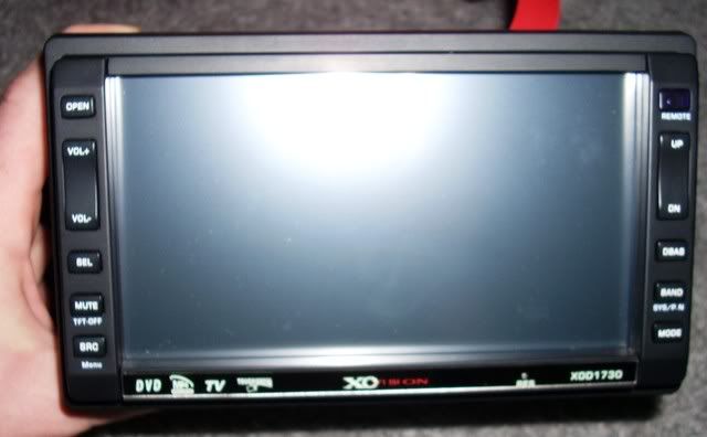
I'm going to install my new Christmas toy today. Anyone have a correct wiring digram for the 2 C4 harnesses? I was just going to splice all the wires and join them to the wires on the new harness with some crimp caps. I can't remember where the different colors go to. If not I guess I'll be using my multimeter to sort them out. It's a non-bose system.
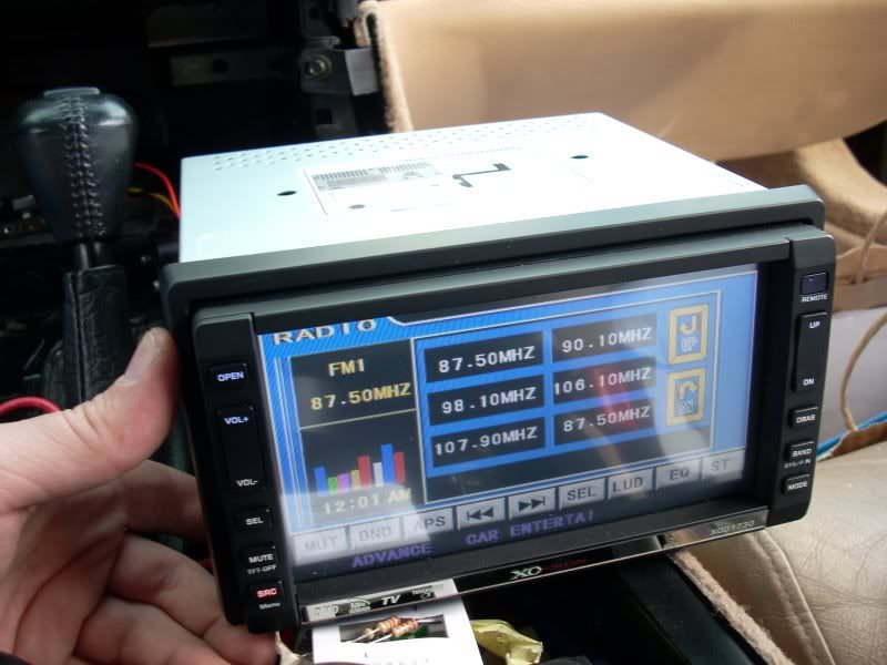
New DVD
Stock Wires
Thanks
New DVD
Stock Wires
Thanks
Last edited by rickneworleansla; 07-04-2011 at 03:41 PM.
 12-28-2007, 05:24 PM
#2
Le Mans Master
Thread Starter
Member Since: Aug 2004
Location: Metairie Louisiana
Posts: 5,141
Likes: 0
Received 4 Likes
on
4 Posts
I found a local shop that has an install wiring harness. I'm going to pick it up tongiht. Hopefully it's color coded to the DVD player harness and that end.
12-29-2007, 03:02 PM
#3
Le Mans Master
Thread Starter
Member Since: Aug 2004
Location: Metairie Louisiana
Posts: 5,141
Likes: 0
Received 4 Likes
on
4 Posts
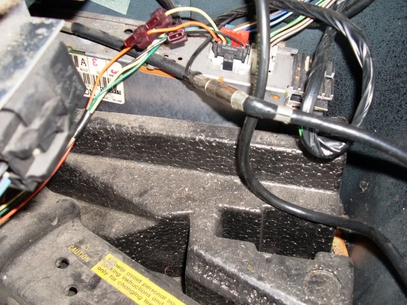
It was the wrong install harness. I guess I may have to just splice into the factory wiring. What is the large metal box behind the factory radio? Is that a factory amp? Do I need to bypass this? Is that why the harness they gave me was incorrect?
Thanks
Thanks
12-29-2007, 08:01 PM
#4
Racer

Member Since: Sep 1999
Location: Conyers Georgia
Posts: 464
Likes: 0
Received 0 Likes
on
0 Posts

The actual radio for your Vette is in the well behind the passengers seat. That is where you need to plug in the harness for power and spekers. Your antenna lead is also there. You will need to extend all of the wires and antenna lead from there to the dash.
12-29-2007, 08:38 PM
#5
Le Mans Master
Thread Starter
Member Since: Aug 2004
Location: Metairie Louisiana
Posts: 5,141
Likes: 0
Received 4 Likes
on
4 Posts
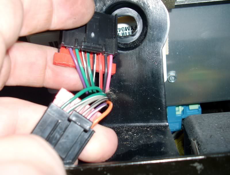
This is what I got so far from the harness that I unplugged from the factory radio. I tested it with a multimeter. That is until one of my leads broke. I'll have to get a new one in the morning. I can't use these wires?
1st harness
Purple=12v with Ignition
Green=10v ??
Brown/White= 0v
Green/White=0v
Black/White=0v
Red/White=12v Constant
Black=Ground
Pink=0v
2nd harness
Orange=12v
Purple/White= Need to Retest
Gray/Black=0v
Gray=Dimmer 5-10v increased with light adjustment
Green/White=5v
Green=0v
Last edited by rickneworleansla; 07-04-2011 at 03:41 PM.
12-31-2007, 11:10 AM
#7
Le Mans Master
Thread Starter
Member Since: Aug 2004
Location: Metairie Louisiana
Posts: 5,141
Likes: 0
Received 4 Likes
on
4 Posts
I finally get home to check my FSM. This is what is listed for the stock in dash radio harness.
C1 12065873
7-way F micro-Pack 100 series
BLK
C2 12064980
9-way F micro-Pack 100 series
BLK
Radio Control Head Unit
---COLOR--------CKT----DESCRIPTION
1--ORN----------440-----BATTERY INPUT
2--PPL/WHT-----1382----LED CONTROL
3--GRY/BLK------1381----LCD CONTROL
4--GRY----------8-------INCANDESCENT LIGHT CONTROL
5--DK GRN/WHT--817-----SPEED COMPENSATED VOLUME CONTROL
6--DK GRN-------835-----DATA LINK
8--PPL-----------1375---IGNITION IN
9--DK GRN-------835-----DATA IN/OUT
10-BRN/WHT-----367-----LEFT AUDIO OUT
11-DK GRN/WHT--368-----RIGHT AUDIO OUT
12-BLK/WHT------372-----AUDIO COMMON
13-RED/WHT-----1364----BATTERY POWER IN
14-BLK-----------1051----RADIO GROUND IN
15-PNK-----------608----+14 VOLTS IN
It looks like I can use...
4--GRY--------For Dimmer Input
8--PPL--------For 12V Input with Ignition On
13-RED/WHT--For Constant 12V Power Source In
14-BLK--------For Radio Ground
I will still need to run new speaker wires. The FSM only lists Left and Right at the harness. I'm wondering how the front/back fade works. Maybe thats what one of those data lines is. I will also need to run the antenna line from the rear compartment reciever. The only thing I'm missing is the antenna line. I think it is the DK GRN with the description DATA IN/OUT. Thats what the wiring diagram is showing in the FSM. Anyone done it this way before? I'm going to try and finish this up today.
I will also need to get rid of the SYS display that comes up without the factory radio installed.
If I'm following the FSM wiring diagram correctly the yellow wire refered to in the transistor fix write up I found is actually the 9-DK GRN-DATA IN/OUT wire on the factory in-dash wiring harness. I got a 10v reading on this when testing with my multimeter. I think this is how it may work... I will connect one end of both resistors to the 9-DK GRN-DATA then one end of one resistor to the 2-PPL/WHT-LED CONTROL and the end of the other resistor to the 3-GRY/BLK-LCD CONTROL.
So what method does everyone use to connect the resistor? Sauder? I've had very bad luck saudering in the past. Will crimp caps work?
Thanks again for everyones help.
Last edited by rickneworleansla; 12-31-2007 at 01:44 PM.
12-31-2007, 06:42 PM
#8
Racer
Member Since: Sep 1999
Location: Conyers Georgia
Posts: 464
Likes: 0
Received 0 Likes
on
0 Posts
Crimp caps will work fine. Here is the fix for the SYS light: http://www.corvetteforum.net/c4/dave8476/index4.shtml
12-31-2007, 07:04 PM
#9
Le Mans Master
Thread Starter
Member Since: Aug 2004
Location: Metairie Louisiana
Posts: 5,141
Likes: 0
Received 4 Likes
on
4 Posts
Crimp caps will work fine. Here is the fix for the SYS light: http://www.corvetteforum.net/c4/dave8476/index4.shtml
I'll have to wait until tomorrow to work on this. I get held up buying last minute fireworks and running to the store. I went for an hour drive today and had no sys light. I wonder if it was just the battery being drained yesterday. I had to jump it after I had the doors open most of the day working on stuff. Radio Shack only had 2.2k Ohm resistors. Maybe I won't have to deal with it after all.
01-03-2008, 04:44 PM
#10
Team Owner

Member Since: Feb 2002
Location: Sometimes I wonder... why is that frisbee getting bigger? Then it hits me.
Posts: 29,701
Received 0 Likes
on
0 Posts
Cruise-In X Veteran
St. Jude Donor '06
Hey don't forget to do a full writeup on the install for reference material for teh how to area. 
Also I swear I saw a converter/connector harness for sale somewhere (probably crutchfield or the likes) that allows you to tie in an aftermarket head units wiring into the stock harness so it is basically plug and play (Ya like it would really be that simple). I will see if I can find it. It might make your life a helluva lot easier than having to splice wires.
Also I swear I saw a converter/connector harness for sale somewhere (probably crutchfield or the likes) that allows you to tie in an aftermarket head units wiring into the stock harness so it is basically plug and play (Ya like it would really be that simple). I will see if I can find it. It might make your life a helluva lot easier than having to splice wires.
Last edited by Madmikeee; 01-03-2008 at 04:48 PM.
01-03-2008, 06:10 PM
#11
Le Mans Master
Thread Starter
Member Since: Aug 2004
Location: Metairie Louisiana
Posts: 5,141
Likes: 0
Received 4 Likes
on
4 Posts
Hey don't forget to do a full writeup on the install for reference material for teh how to area.
Also I swear I saw a converter/connector harness for sale somewhere (probably crutchfield or the likes) that allows you to tie in an aftermarket head units wiring into the stock harness so it is basically plug and play (Ya like it would really be that simple). I will see if I can find it. It might make your life a helluva lot easier than having to splice wires.
Also I swear I saw a converter/connector harness for sale somewhere (probably crutchfield or the likes) that allows you to tie in an aftermarket head units wiring into the stock harness so it is basically plug and play (Ya like it would really be that simple). I will see if I can find it. It might make your life a helluva lot easier than having to splice wires.
It looks like I'll have to do the SYS delete thing anyway. It does still come on but it seems to be intermittent or maybe it just shows on startup.?
01-04-2008, 04:17 PM
#12
Team Owner
Member Since: Feb 2002
Location: Sometimes I wonder... why is that frisbee getting bigger? Then it hits me.
Posts: 29,701
Received 0 Likes
on
0 Posts
Cruise-In X Veteran
St. Jude Donor '06
I'll be sure to do the write up when finished. I always take pictures along the way of most installs. The next day was freezin outside so I decided to wait for this weekend. It should be back in the 70's by Saturday. It looks like I'll have to do the SYS delete thing anyway. It does still come on but it seems to be intermittent or maybe it just shows on startup.?
It looks like I'll have to do the SYS delete thing anyway. It does still come on but it seems to be intermittent or maybe it just shows on startup.?  01-05-2008, 05:32 PM
#13
Heel & Toe

Member Since: Aug 2005
Location: Honolulu Hawaii
Posts: 19
Likes: 0
Received 0 Likes
on
0 Posts
The "SYS" indicator indicated when the battery was drained. After you jumped start and drove for a while, the battery charge was resorted to proper operating levels and the "SYS" indicator did not display. When you replace the Head Unit you may or may not receive a "SYS" indication. If you do, then follow the advice referenced in the thread. I strongly suggest that you disconnect the battery while doing the rewiring associated with the installation of the new Head Unit.
 01-08-2008, 05:54 PM
#16
Le Mans Master
Thread Starter
Member Since: Aug 2004
Location: Metairie Louisiana
Posts: 5,141
Likes: 0
Received 4 Likes
on
4 Posts
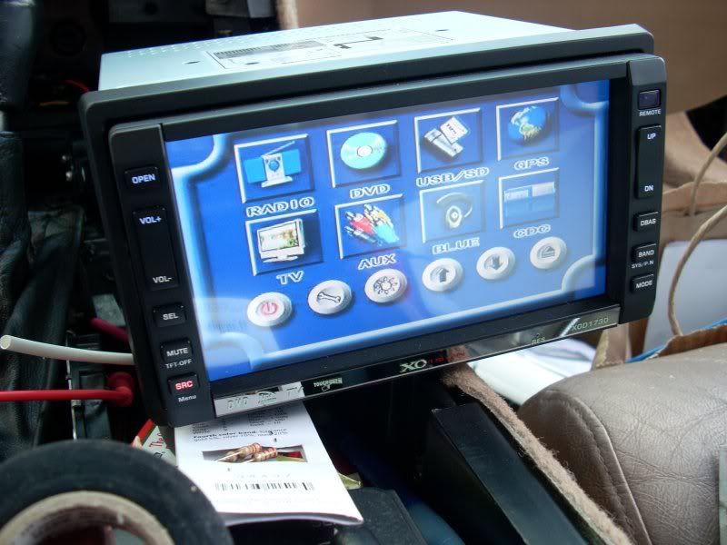
More pics.
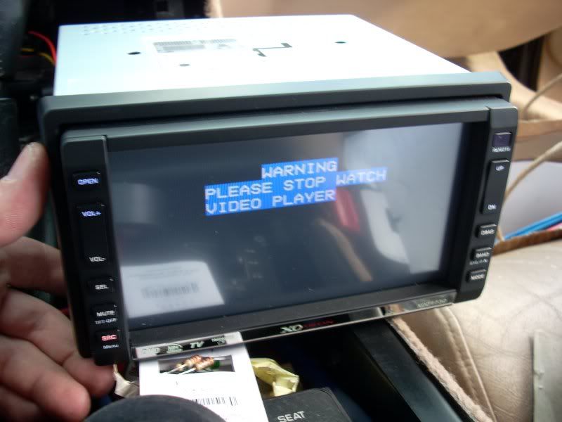
I probably need to bypass the saftey.
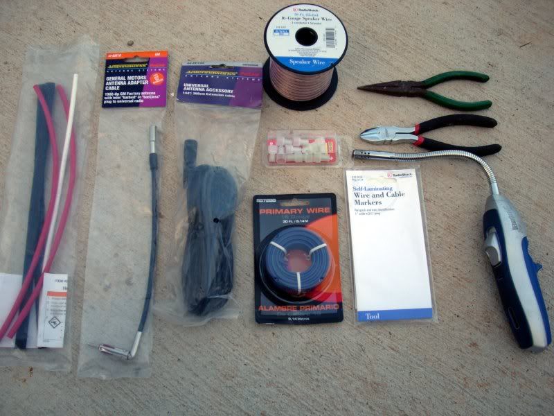
Some install items.
Wiring diagram.
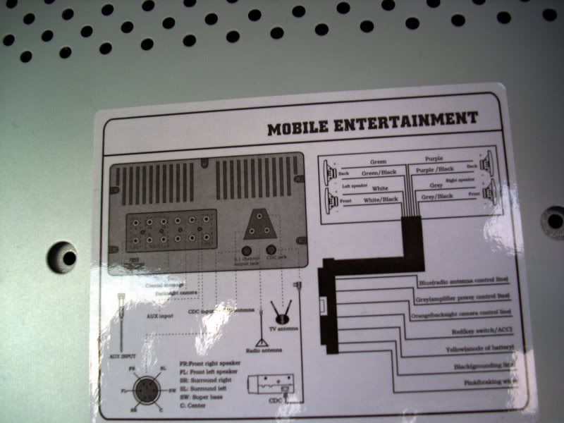
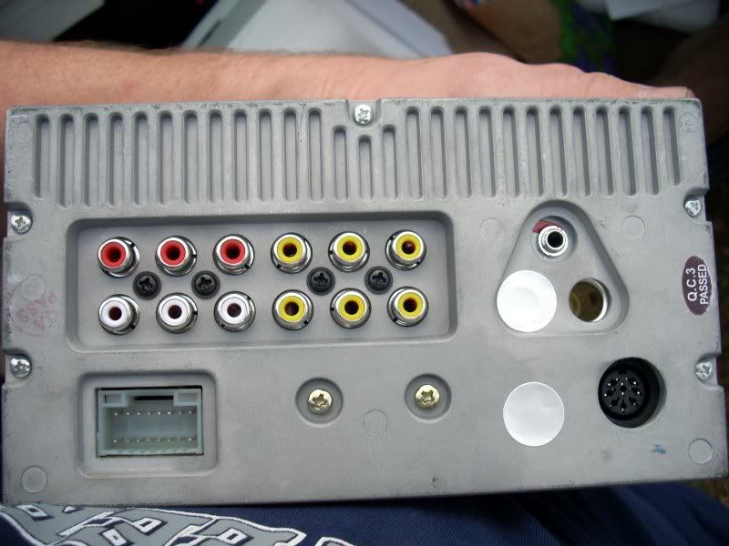
Rear Inputs.
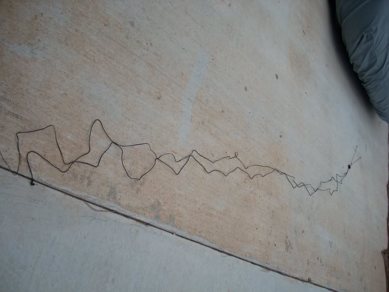
It came with this TV antenna. Now where the heck am going to install this thing at. Maybe in the rear cargo area. I guess this won't do me much good anyway after February 2009 when everything switches to hi-def. I'll have to research how those converter boxes work.
My attempt at the SYS warning fix. It did not work probably because I used 2.2k Ohm resistors. Radio shack only carries those now. I'll be picking up the correct 2k Ohm resistors this week off the internet. I wanted to redo this a little better anyway.
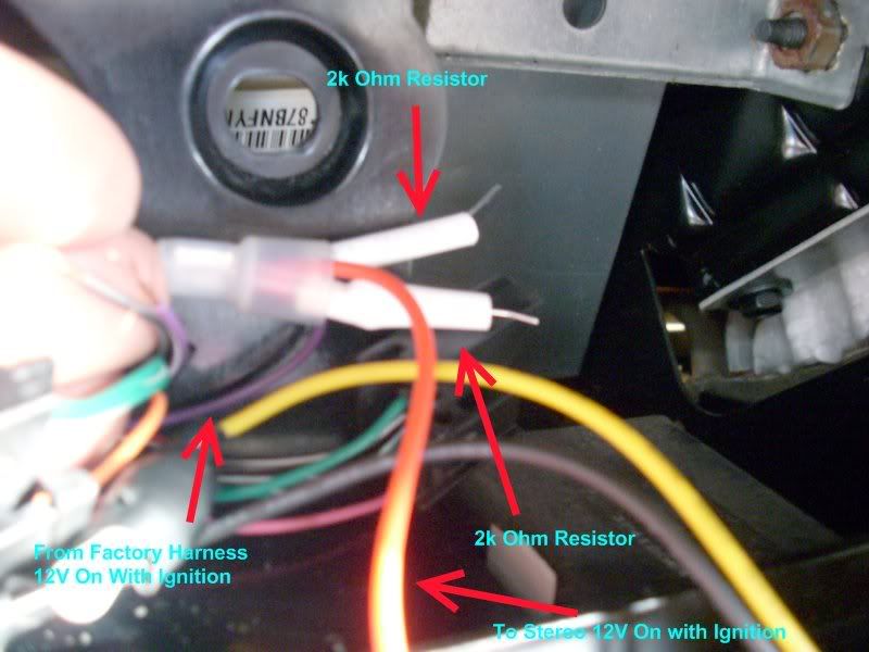
Not shown here but I also wrapped the whole thing in electrical tape when done.
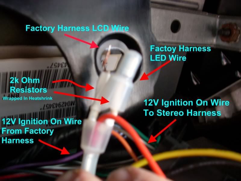
I used crimp caps, heat shrink tubing, and electrical tape on everything. I bought the wrong size crimp caps but they will work ok for now.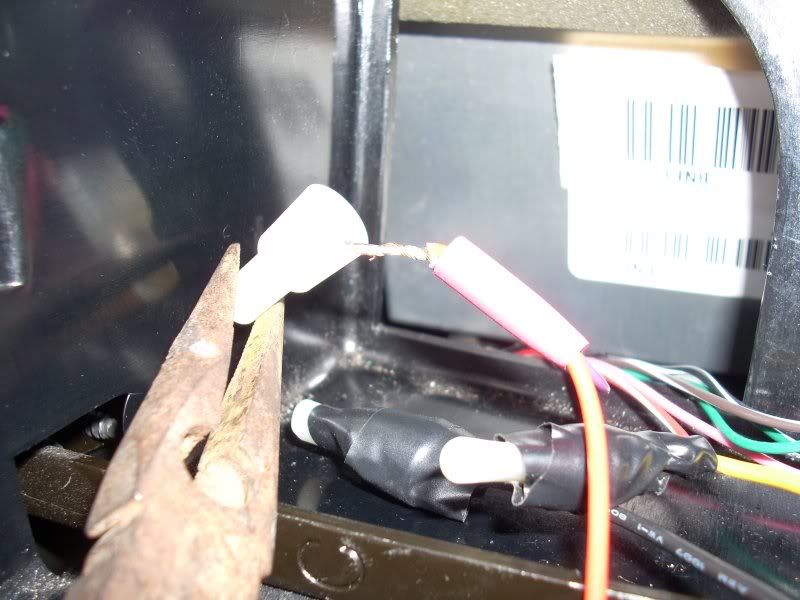
Work in progress. More to come.....
I probably need to bypass the saftey.
Some install items.
Wiring diagram.
Rear Inputs.
It came with this TV antenna. Now where the heck am going to install this thing at. Maybe in the rear cargo area. I guess this won't do me much good anyway after February 2009 when everything switches to hi-def. I'll have to research how those converter boxes work.
My attempt at the SYS warning fix. It did not work probably because I used 2.2k Ohm resistors. Radio shack only carries those now. I'll be picking up the correct 2k Ohm resistors this week off the internet. I wanted to redo this a little better anyway.
Not shown here but I also wrapped the whole thing in electrical tape when done.
I used crimp caps, heat shrink tubing, and electrical tape on everything. I bought the wrong size crimp caps but they will work ok for now.
Work in progress. More to come.....
Last edited by rickneworleansla; 12-30-2010 at 05:08 PM.
01-09-2008, 11:02 AM
#17
Team Owner
Member Since: Feb 2002
Location: Sometimes I wonder... why is that frisbee getting bigger? Then it hits me.
Posts: 29,701
Received 0 Likes
on
0 Posts
Cruise-In X Veteran
St. Jude Donor '06
obviously you didn't find any harness adapters then huh? 
Can't wait to see more
Can't wait to see more
01-09-2008, 12:20 PM
#18
Le Mans Master
Thread Starter
Member Since: Aug 2004
Location: Metairie Louisiana
Posts: 5,141
Likes: 0
Received 4 Likes
on
4 Posts
