
 03-25-2015, 01:48 PM
Last edit by: IB Advertising
See related guides and technical advice from our community experts:
Browse all: Interior How-Tos
- C6 Corvette: How to Install an Amplifier
Step by step instructions for do-it-yourselfers...
Browse all: Interior How-Tos

C5 and general audio FAQ
03-12-2006, 06:34 PM
#41
Racer


Member Since: Nov 2004
Location: TX
Posts: 395
Likes: 0
Received 0 Likes
on
0 Posts
Originally Posted by V7TTE
Hi All,
As a UK Vette driver with a US-import car (i.e. not Euro spec) the radio only tunes to frequencies that are "odd" (i.e. 94.9 104.9 etc).
Does anybody know if this can be changed so it picks up "even" number frequencies?? I gues this may not be a problem for you guys, but it is a pain for us, as many of our major stations broadcast on the even numbers
I hope there may be an answer other than "throw it away and replace"!!!


 07-18-2006, 05:59 PM
#43
8th Gear

Member Since: Jul 2006
Location: bloomington IN
Posts: 8
Likes: 0
Received 0 Likes
on
0 Posts
what i want to do is upgrade speakers without replacing head or amp.......i've read abit on this but found it hard to come to a conclusion with regards to Bose units. Thanks for some info.........
scott
98 cooooop
scott
98 cooooop
07-18-2006, 07:34 PM
#44
Le Mans Master

Thread Starter

as a note for anyone in the future...please don't just ask questions in this section... it will get cluttered up and make it harder for people to find answers. please post any questions in a dedicated thread.
thank you.
sbayer... i'll answer your question in your thread
thank you.
sbayer... i'll answer your question in your thread
08-06-2006, 09:18 PM
#45

*only ten pics can be posted per post, so this will have to be broken up into a few sections.
How to install a aftermarket HU into a C5 and keep all the Bose speakers, including the door subs.
The alpine 9856 with be the HU used in this install.
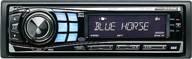
The HU was bought from crutchfield.com.
It came with
Chev/GMC install kit # 120993300
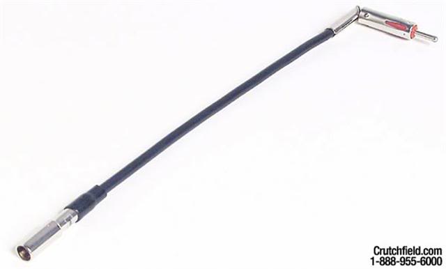
GM antenna adaptor #12040GM10
General Motors Receiver Wire Harness #120701858 (this will not be used)
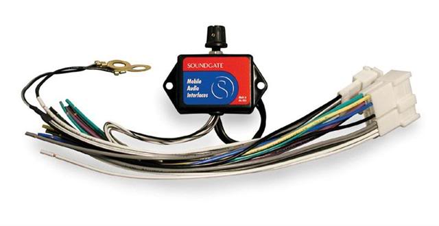
I used the Soundgate GMCRV1 installation wire/kit to hook every thing up.
And some extra wire I had around for some extension pieces (optional).
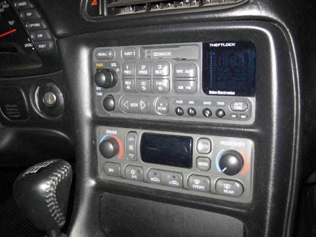
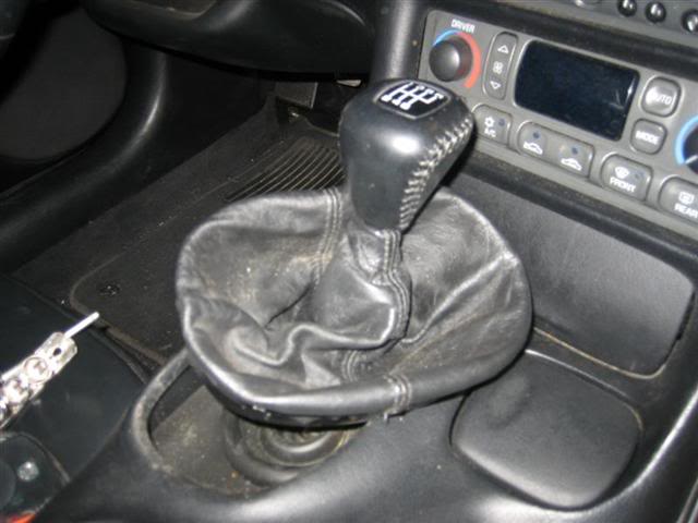
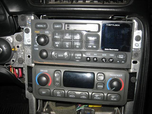
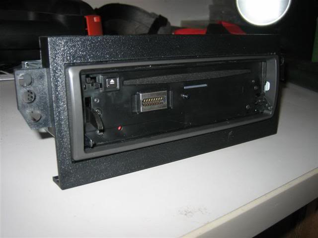
First here is a before pic.
Set parking brake and disconnect negative batter cable.
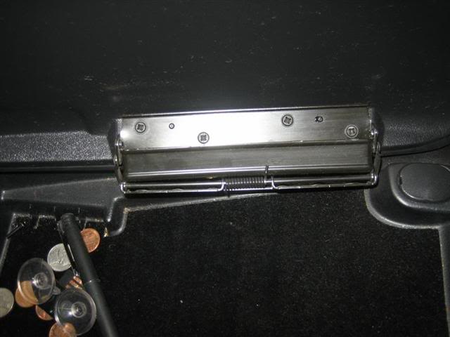
Open center console door and remove the 4 screws that hold on the lid.
Pry up the traction control panel.
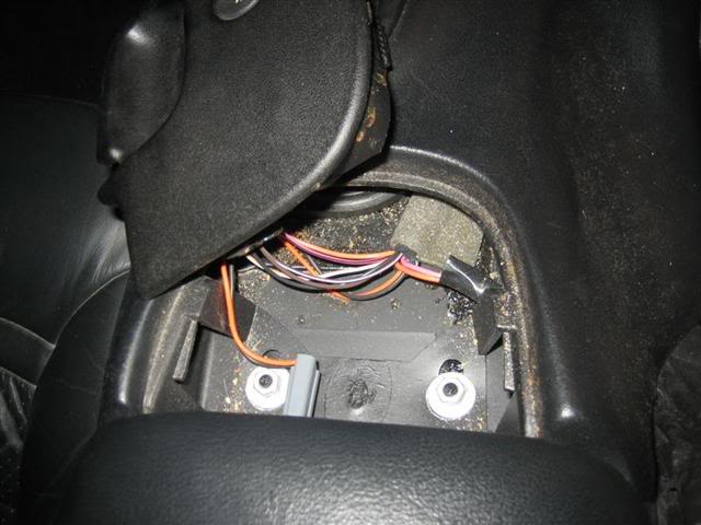
Disconnect the wire harness.
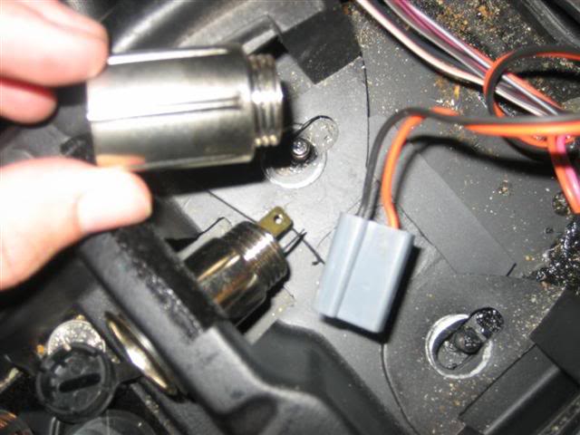
Disconnect the 12 volt accessory wire harness and unscrew/remove unit.
Remove 2 10mm nuts.
Open ashtray/lighter door and remove ashtray. Remove the two torx screws.
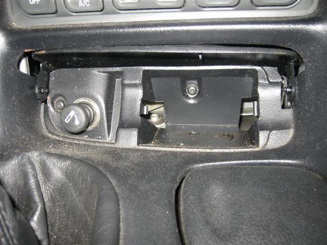
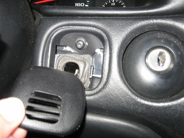
Pry off small panel that is left of the ignition. Remove one torx screw.
How to install a aftermarket HU into a C5 and keep all the Bose speakers, including the door subs.
The alpine 9856 with be the HU used in this install.
The HU was bought from crutchfield.com.
It came with
Chev/GMC install kit # 120993300
GM antenna adaptor #12040GM10
General Motors Receiver Wire Harness #120701858 (this will not be used)
I used the Soundgate GMCRV1 installation wire/kit to hook every thing up.
And some extra wire I had around for some extension pieces (optional).
First here is a before pic.
Set parking brake and disconnect negative batter cable.
Open center console door and remove the 4 screws that hold on the lid.
Pry up the traction control panel.
Disconnect the wire harness.
Disconnect the 12 volt accessory wire harness and unscrew/remove unit.
Remove 2 10mm nuts.
Open ashtray/lighter door and remove ashtray. Remove the two torx screws.
Pry off small panel that is left of the ignition. Remove one torx screw.
08-06-2006, 09:18 PM
#46
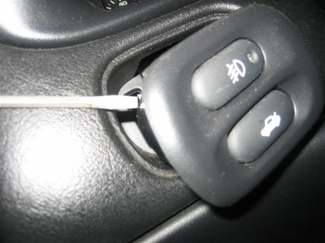
Pry off small panel to the left of the steering column, that has the hatch and fog light buttons.
Remove one torx screw. Disconnect wire harness.
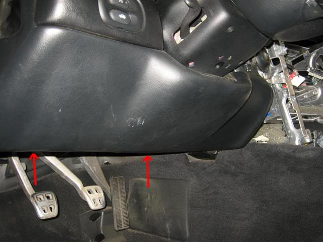
Remove the 2 screws on the bottom of the driver side knee panel.
Disconnect wire from sensor on right side. Pull out knee panel.
Loosen ring around bottom of shift lever boot and slide boot upward (no need to remove shift ****)
Lift the counsel panel from the rear until it clears above the fuel switch button.
Push shift boot through the opening
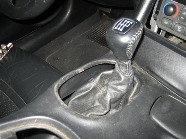
Then pull back on the panel until it is fully removed.
Be careful not to break the small plastic pegs attached to the console, that are located to the left and right of the opening for the stereo.
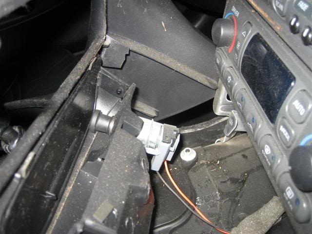
Unhook wire from back of cigarette lighter.
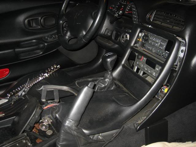
Remove the two 7mm screws that hold the stereo in place, and the two 7mm screws for the climate control.
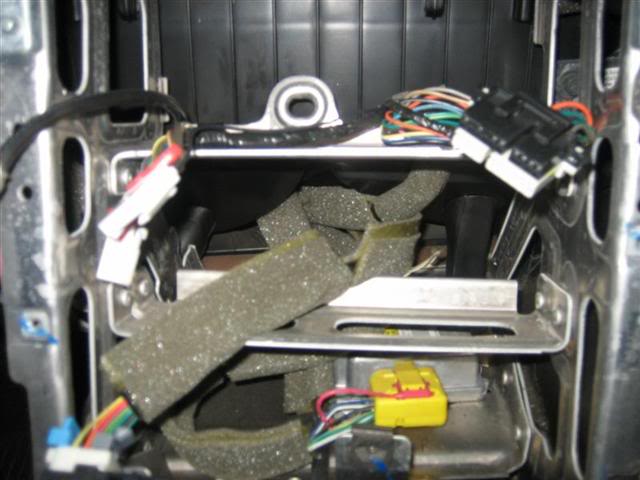
Unhook wires from back of stock stereo and climate controls. And pull out stereo and climate controls.
Remove passenger side floor mat, remove carpet panel from front of passenger foot well.
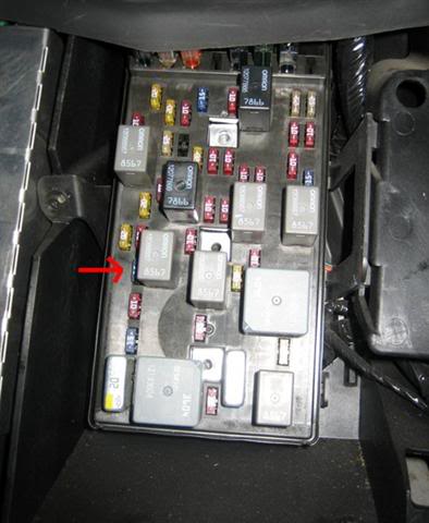
Remove fuse box cover, and pull fuse #5 (RDO/CD).
In my pic, the fuse is small, blue, and kind of hidden.
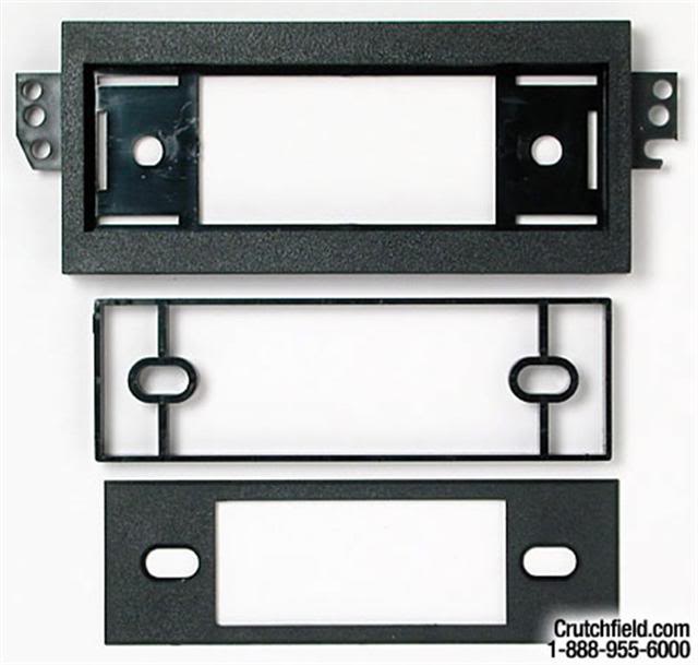
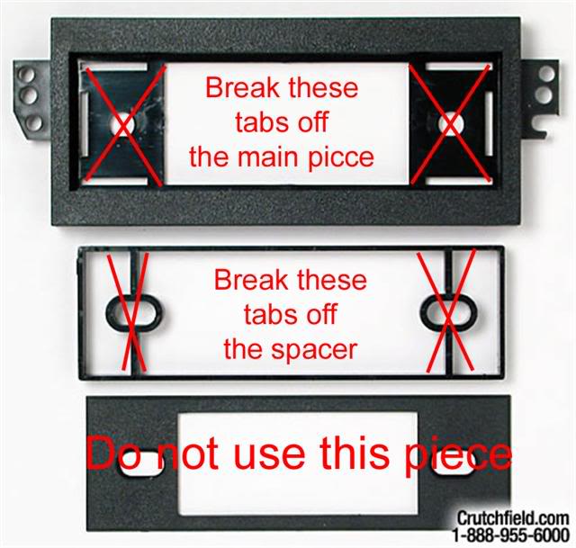
Preparing black plastic install kit:
Break off left and right piece on main and spacer piece.
The third price is not used.
Remove one torx screw. Disconnect wire harness.
Remove the 2 screws on the bottom of the driver side knee panel.
Disconnect wire from sensor on right side. Pull out knee panel.
Loosen ring around bottom of shift lever boot and slide boot upward (no need to remove shift ****)
Lift the counsel panel from the rear until it clears above the fuel switch button.
Push shift boot through the opening
Then pull back on the panel until it is fully removed.
Be careful not to break the small plastic pegs attached to the console, that are located to the left and right of the opening for the stereo.
Unhook wire from back of cigarette lighter.
Remove the two 7mm screws that hold the stereo in place, and the two 7mm screws for the climate control.
Unhook wires from back of stock stereo and climate controls. And pull out stereo and climate controls.
Remove passenger side floor mat, remove carpet panel from front of passenger foot well.
Remove fuse box cover, and pull fuse #5 (RDO/CD).
In my pic, the fuse is small, blue, and kind of hidden.
Preparing black plastic install kit:
Break off left and right piece on main and spacer piece.
The third price is not used.
08-06-2006, 09:19 PM
#47
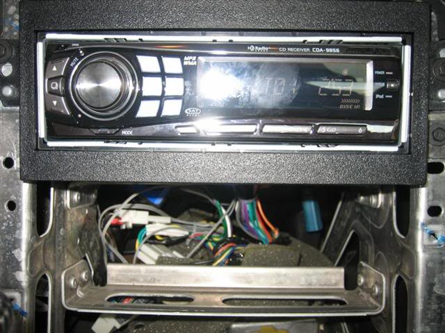
Place the spacer into the main piece and then slide the HU into it.
If the spacer is not use the HU will set to far back into the dash, and not fit.
Bend the tabs on the outer metal casing of the HU to hold it to the install kit.
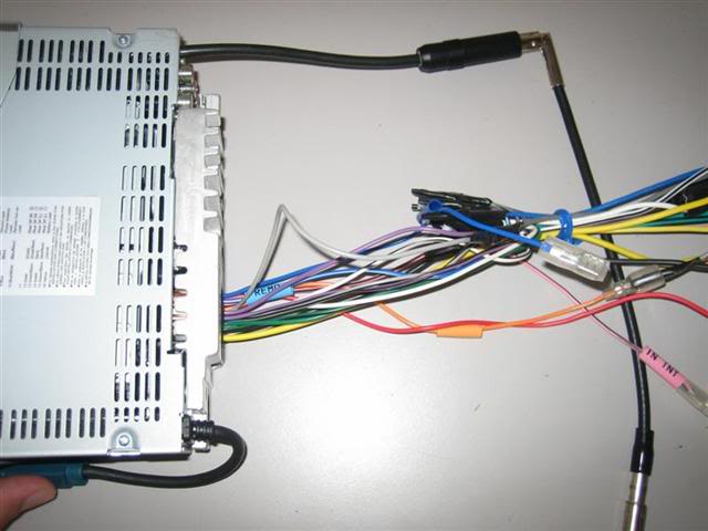
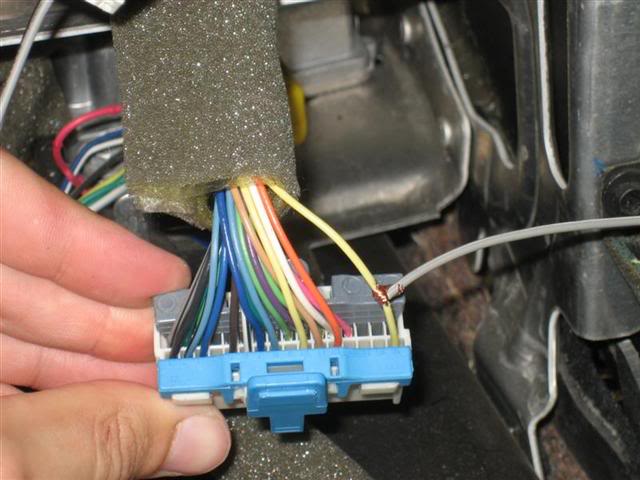
Connect Soundgate GMCRV1 wire harness to aftermarket HU wires.
Purple = right rear positive
Purple/Black = right rear negative
Green = left rear positive
Green/Black = left rear negative
Gray = right front positive
Gray/Black = right front negative
White = left front positive
White/Black = left front negative
Connect blue wire of GMCRV1 to �amplifier tune-on� wire of new HU, or if the new HU does not have this lead, connect to �power antenna� of new HU. These wire are usually blue/white and blue.
Connect �battery� wire (typically yellow) of new HU to yellow wire on the GMCRV1.
Connect Antenna adaptor.
*pic shows everything soldered together, and snapped into the back of the HU.
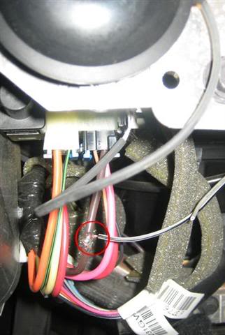
Connect �power� wire (typically red) of new HU to the wire under the dash that supplied +12 volts when the ignition key is in �RUN�. This wire can be found ignition, and is brown in color. A millimeter can test the voltage to make sure it is the correct one.
I used a razor blade to stripe away some of the wire covering, then used an extra extension piece of gray wire between the �brown ignition wire� and the �red HU power wire�. That way I can pull out the HU all the when needed. Solder and tape the connection.
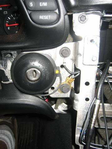
Connect to 2 ground wires to the bottom screw to the right of the ignition. And the ground wire from the HU to the top screw.
Connect the illumination wire to the cream colored wire on the climate control harness. (optional). Solder and tape the connection. Once again I use an extra extension piece gray of wire, incase I needed to pull the HU out. That is why the wire connecting to the cream climate control wire is gray.
Note from Soundgate�s install guide: If you have a 1999 or newer Vette and you do not get output from the factory door woofers, you will need to move the ground wire on the 9-pin harness from the end it is on, to the other end.
*I have a 1999 and did not have to do this.
Plug in all harnesses.
Reinstall fuse in passenger foot well.
Reconnect negative battery cable.
And test out the HU to make sure everything works.
Adjust the gain **** on the Soundgate box to your desired setting. This box gets put into the dash when done, and will not be accessible when fished. (unless you find a spot to mount in, and possible extent the wire, I did not do this, I just put mine behind the HU)
Zip tie all wires together to they do not make a mess when pushing them back into the dash.
As you can see I have plenty of room, to pull the HU out. If I would not have used the extension wires on the power and illumination, the HU would not be able to come out that far.
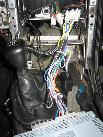
Push wires and HU into dash. Use the space from he removed Climate control to help guide the wires down (there is a lot of room behind the climate controls for the wires to go).
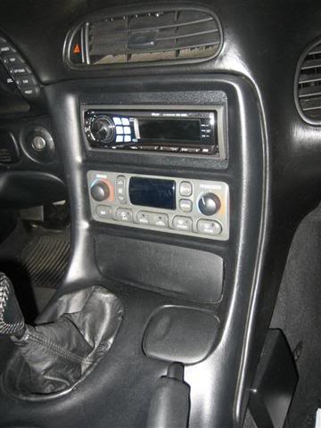
Screw in HU and Climate controls.
Reassemble all dash and console parts.
*small note. When I first hooked every thing up, I did not get any sound from the sub woofers.
I had to turn up the bass for the subs to activate.
There is a note on the Soundgate instructions that say, your HU has to have
high power outputs, so that is prob the reason, you need the bass turned up.
I don't know if that is the case for sure, but it worked for me.
If you have problems with the install you can send me a message, but if you cant get the Soungate device to work properly, it might work best to contact them.
If the spacer is not use the HU will set to far back into the dash, and not fit.
Bend the tabs on the outer metal casing of the HU to hold it to the install kit.
Connect Soundgate GMCRV1 wire harness to aftermarket HU wires.
Purple = right rear positive
Purple/Black = right rear negative
Green = left rear positive
Green/Black = left rear negative
Gray = right front positive
Gray/Black = right front negative
White = left front positive
White/Black = left front negative
Connect blue wire of GMCRV1 to �amplifier tune-on� wire of new HU, or if the new HU does not have this lead, connect to �power antenna� of new HU. These wire are usually blue/white and blue.
Connect �battery� wire (typically yellow) of new HU to yellow wire on the GMCRV1.
Connect Antenna adaptor.
*pic shows everything soldered together, and snapped into the back of the HU.
Connect �power� wire (typically red) of new HU to the wire under the dash that supplied +12 volts when the ignition key is in �RUN�. This wire can be found ignition, and is brown in color. A millimeter can test the voltage to make sure it is the correct one.
I used a razor blade to stripe away some of the wire covering, then used an extra extension piece of gray wire between the �brown ignition wire� and the �red HU power wire�. That way I can pull out the HU all the when needed. Solder and tape the connection.
Connect to 2 ground wires to the bottom screw to the right of the ignition. And the ground wire from the HU to the top screw.
Connect the illumination wire to the cream colored wire on the climate control harness. (optional). Solder and tape the connection. Once again I use an extra extension piece gray of wire, incase I needed to pull the HU out. That is why the wire connecting to the cream climate control wire is gray.
Note from Soundgate�s install guide: If you have a 1999 or newer Vette and you do not get output from the factory door woofers, you will need to move the ground wire on the 9-pin harness from the end it is on, to the other end.
*I have a 1999 and did not have to do this.
Plug in all harnesses.
Reinstall fuse in passenger foot well.
Reconnect negative battery cable.
And test out the HU to make sure everything works.
Adjust the gain **** on the Soundgate box to your desired setting. This box gets put into the dash when done, and will not be accessible when fished. (unless you find a spot to mount in, and possible extent the wire, I did not do this, I just put mine behind the HU)
Zip tie all wires together to they do not make a mess when pushing them back into the dash.
As you can see I have plenty of room, to pull the HU out. If I would not have used the extension wires on the power and illumination, the HU would not be able to come out that far.
Push wires and HU into dash. Use the space from he removed Climate control to help guide the wires down (there is a lot of room behind the climate controls for the wires to go).
Screw in HU and Climate controls.
Reassemble all dash and console parts.
*small note. When I first hooked every thing up, I did not get any sound from the sub woofers.
I had to turn up the bass for the subs to activate.
There is a note on the Soundgate instructions that say, your HU has to have
high power outputs, so that is prob the reason, you need the bass turned up.
I don't know if that is the case for sure, but it worked for me.
If you have problems with the install you can send me a message, but if you cant get the Soungate device to work properly, it might work best to contact them.
 08-14-2006, 05:20 PM
#49
Team Owner


This is something unique to the C5 and C6, but there seems to be a ton of adaptors for the Bose... if not connecting aftermarket bits to the bose, it's replacing the head... or interfacing an iPod.
Can a master list of these adaptors, manufacturer info and description be created?
Just an idea.
Can a master list of these adaptors, manufacturer info and description be created?
Just an idea.
08-16-2006, 11:11 PM
#50
Le Mans Master
Here is a link to a somewhat in depth C5 install
http://forums.corvetteforum.com/show....php?t=1469707
and another with some nice pics
http://forums.corvetteforum.com/show....php?t=1558079
Dbl Din in a C5
http://forums.corvetteforum.com/show....php?t=1687832
Another nice C5 system
http://forums.corvetteforum.com/show....php?t=1691871
A full out Elemental Designs system
http://forums.corvetteforum.com/show....php?t=1747685
Another C5 install, but a little bit more mild
http://forums.corvetteforum.com/show....php?t=1707771
A nice C5 Z install
http://forums.corvetteforum.com/show...post1565533880
A little FRC install
http://forums.corvetteforum.com/show....php?t=2066612
Last edited by pentavolvo; 07-01-2008 at 08:59 PM.
09-20-2006, 11:26 AM
#51
4th Gear

Member Since: Apr 2005
Posts: 4
Likes: 0
Received 0 Likes
on
0 Posts
Hello all in ref to this issues:I have a navigation h/u that has to connect to a speed sensor wire, where is it?
You will have to tap into the harness on the instrument cluster. You need to find the Green/white (A7-circuit 817) with a tan/white (A6-circuit 33) above it and a black (A8-circuit 150 ) below it..The other green/white (A10-circuit 357) oil temp has a blank and a gray on each
side.
anyone have reached this wire and know where it is??
thanks, Ruben
09-25-2006, 03:40 PM
#52
Former Vendor
Member Since: Nov 2005
Location: Spring Texas
Posts: 8,995
Likes: 0
Received 2 Likes
on
2 Posts
St. Jude Donor '08
What RCA cables do you reccomend for hooking up sound systems. should i consider using a different set/style for a subwoofer vs a midrange speaker?
thanks
thanks
10-01-2006, 11:19 AM
#53
Former Vendor
Member Since: Nov 2005
Location: Murfreesboro, TN. "I'm like a kid in a candy store everytime I see a Corvette!!"
Posts: 411
Likes: 0
Received 0 Likes
on
0 Posts
Originally Posted by bogus
This is something unique to the C5 and C6, but there seems to be a ton of adaptors for the Bose... if not connecting aftermarket bits to the bose, it's replacing the head... or interfacing an iPod.
Can a master list of these adaptors, manufacturer info and description be created?
Just an idea.
Can a master list of these adaptors, manufacturer info and description be created?
Just an idea.

Enjoy!! Master C5 Adapter List
 01-15-2007, 11:14 PM
#57
Drifting


Is that speaker mount a modified version of the one that came with the car? Where can you get it if not ? Same goes with the tweeter mount ? Did you just drill out the spot for the tweeter ? These vrumvrum parts too ? 
thanks!
EDIT: I see that those speakers and crossover are JL audio. Now I just need to know how to mount it like you have shown here.
thanks!
EDIT: I see that those speakers and crossover are JL audio. Now I just need to know how to mount it like you have shown here.
01-27-2007, 05:24 PM
#58
1st Gear

Member Since: Jan 2007
Posts: 1
Likes: 0
Received 0 Likes
on
0 Posts
First of all, I just want to thank vetteessentials.com and corvetteforum.com and all of its members because there is no way I would have been able to do this project without a community of people helping each other out like this one.
My car is a 2001 Z06. I removed the factory Bose H/U and the door speakers. I installed an Alpine 9857 H/U and Infinity Reference 6012i's in the doors. I bought some fiberboard templates from a local shop for the speakers so that they could fit into the huge factory holes. I also ran new speaker wire, as the Bose system only has thin little signal wires because (as I understand it) there is no amplifier in the stereo.
For the door speaker swap: Start by removing the door panels. This procedure is explained best by vetteessentials http://www.vetteessentials.com/instr...structions.htm. They are extremely detialed and show good pictures. Be careful not to break those cheap-*** little plastic snap-fit rods that hold the door panel on. I broke 2 out of 12 when I did it.
As you can see, there are 6 screws that hold the speaker housing onto the door. One mistake that I made was I completely disassembled the subassembly of the speaker housing, removing the speaker, the tweeter, and then I finally realized all you have to do is remove these 6 screws. Then you are going to have use some force to get the housing off of the door because it is glued on. After that, make sure that before you put your template on, you put some weather strip insulation stuff on the contact surfaces. If you bought new speakers, this stuff should come with it, but if you need some more you can get it at any hardware store. I never did figure out a good way to line up the screws into the template onto the door. I just kind of eyeballed it. I'm sure there is an efficient way of doing this, but I didn't know of one. Then once you get the template on there you need to run your new speaker wire. With the door open, look at the hinges and you will see the rubber tube that carries all of the wires from the car to the door. Feel up the wall on the inside of the car where you think that tube enters the car and you should see/feel a 3 inch by 3 inch piece of plastic with a hole at the top of it where the wires come into the car. That piece of plastic pops right out with a little force. Read jawzforlife's post in this thread to see how to remove the dash piece under the steering column. Then you can run the speaker wire up behind the H/U. The passenger side is very similar.
For the H/U swap: I got all of my information from this thread, so read through it first. The parts you will need are the GM attenna adapter, the stereo installation kit (the plastic surround thing that allows you to mount the H/U to the car and makes it look flush), and the wiring harness. To remove the factory H/U, read the other posts in this thread, as well as the instruction booklet for the installation kit that you bought. When you get the factory H/U out, notice that there are two harnesses plugged into it. I don't know what the point is of the smaller one, but you don't need it (it probably has something to do with the Bose system). Ok, what you need to wire a H/U is power, ground, ignition, and speaker(s). The only thing I used the factory harness for was power. I got the ground from the left screw that holds the H/U to the car. I got ignition from the brown wire like jawzforlife describes in this thread. I ran my own speaker wire, so I didn't use the factory harness for speakers either. I blew it off to save time, but if I were to try to hook up the illumination, I would use the HVAC wire like jawzforlife describes. After that you are good to go. Make sure you reconnect all of the accessory button wires that you had to disconnect to remove the dash and console (i.e. trunk release button, fuel cap release, etc.) because evidently I didn't hook up my fuel cap release, and now I have to use the manual override until I have time to tear it all apart again. Anyways... I hope this helps. For pictures go here:
http://new.photos.yahoo.com/jimmyfleenor/photo
01-30-2007, 07:41 PM
#59
Le Mans Master
BIG 3 Upgrade
Lately the topic of the big 3 has been getting alot of talk. This is something everyone with big stereos should be doing before they remotely consider bigger alternators or especially a god damn capacitor. First off this thread covers the basics http://forum.sounddomain.com/ubb/ult...c;f=5;t=007801
More aless what happens is your stock wiring is barely big enough to power the damn car now we add more current draw and its a huge bottleneck. So in essence what we do is add on to the stock wiring with either 4ga or 0ga. IMO 4ga is more then enough and 0ga just makes for more work.
First off if you have sidepost terminals and havent already gotten gm sidepost adapters do it that will make this much easier. Run a wire from the terminal off the alternator to the battery positive terminal and cover it in wire loom or sheath or something of that nature. Some will run it around the frong of the motor by the fan shroud, some will go around the back and others will go straight accross.
To get the wire into the are surrounding the battery towards the bottom u can slide it through, and that plastic piece comes off easily if you pop a pin or 2 out to make working much easier, some will opt to drill holes in the side of the plastic as well. I prefer to remove the piece and notch the bottom a bit to get the wiring to the battery, it makes it a little easier to hide it.
You also want to beef up the grounds. Basically the connection from the motor block (alternator mounting bolt works great) to the frame and the frame to the battery. Or engine to battery and frame to battery its all the same in the end. Some will run a wire straight from the alternaotr mounting bolt straight to ground on the battery and then from ground on battery to a frame ground. They can be easily found all over the car. I know there is one right near the battery somewhere as well as up towards the front by the washer resevoir there are a few. Sorry I dont have bettery specifics but this should deff help everyone with a start. Make sure to scrape off any paint from the frame for your ground before you make your connection.
Here are some pics stolen from forum member TheRadioFlyer
Alternator bracket (ground in front power wire in rear)

battery ground wire

Another thread regarding big 3 (DPG) http://forums.corvetteforum.com/show...ighlight=big+3
Lately the topic of the big 3 has been getting alot of talk. This is something everyone with big stereos should be doing before they remotely consider bigger alternators or especially a god damn capacitor. First off this thread covers the basics http://forum.sounddomain.com/ubb/ult...c;f=5;t=007801
More aless what happens is your stock wiring is barely big enough to power the damn car now we add more current draw and its a huge bottleneck. So in essence what we do is add on to the stock wiring with either 4ga or 0ga. IMO 4ga is more then enough and 0ga just makes for more work.
First off if you have sidepost terminals and havent already gotten gm sidepost adapters do it that will make this much easier. Run a wire from the terminal off the alternator to the battery positive terminal and cover it in wire loom or sheath or something of that nature. Some will run it around the frong of the motor by the fan shroud, some will go around the back and others will go straight accross.
To get the wire into the are surrounding the battery towards the bottom u can slide it through, and that plastic piece comes off easily if you pop a pin or 2 out to make working much easier, some will opt to drill holes in the side of the plastic as well. I prefer to remove the piece and notch the bottom a bit to get the wiring to the battery, it makes it a little easier to hide it.
You also want to beef up the grounds. Basically the connection from the motor block (alternator mounting bolt works great) to the frame and the frame to the battery. Or engine to battery and frame to battery its all the same in the end. Some will run a wire straight from the alternaotr mounting bolt straight to ground on the battery and then from ground on battery to a frame ground. They can be easily found all over the car. I know there is one right near the battery somewhere as well as up towards the front by the washer resevoir there are a few. Sorry I dont have bettery specifics but this should deff help everyone with a start. Make sure to scrape off any paint from the frame for your ground before you make your connection.
Here are some pics stolen from forum member TheRadioFlyer
Alternator bracket (ground in front power wire in rear)
battery ground wire
Another thread regarding big 3 (DPG) http://forums.corvetteforum.com/show...ighlight=big+3
Last edited by pentavolvo; 04-12-2007 at 09:54 PM.
03-24-2007, 12:58 AM
#60
Melting Slicks

For those of you that wonder how deep you can go before you hit the window / window track / other obstruction:
Here is a picture of my drivers side door. All measurements are from the outer edge inward, and have a built in 'fudge factor' to prevent contact between the speaker magnet and the door parts.
Keep in mind that your window may be adjusted differently from the factory than mine is.... so always check before making final fitments.

Higher resolution picture can be found here:
http://www.fasthotrod.mypldi.net/ima...tte%20Door.JPG
Hope this helps.
Mark
Here is a picture of my drivers side door. All measurements are from the outer edge inward, and have a built in 'fudge factor' to prevent contact between the speaker magnet and the door parts.
Keep in mind that your window may be adjusted differently from the factory than mine is.... so always check before making final fitments.
Higher resolution picture can be found here:
http://www.fasthotrod.mypldi.net/ima...tte%20Door.JPG
Hope this helps.
Mark
Last edited by Fasthotrod; 12-16-2007 at 02:05 AM.