ratty 86 advice needed
 01-28-2014, 03:15 PM
#1
Intermediate

Thread Starter

Member Since: Jan 2014
Location: Garfield Arkansas
Posts: 36
Likes: 0
Received 0 Likes
on
0 Posts
Brother-in-law asked me to look at a ratty 86 auto coupe he just bought for $300 that has had lots of fiddling with the wiring including a couple of red wires near but not connected to the pos battery cable and a bunch of wire splices on an empty female multiple connector just inboard of the battery.
The gages come on, but no fuel pump sound and no crank with a freshly charged battery. I reconnected the center panel and it can change the gage functions, but whatever was below it is gone (radio I suppose?).
Not sure where to start. I searched here but didn't find how to check for codes. I have an Actron code reader, but didn't see an OBD plug. The seller told him it did run once, and he had $$$ work done on the front suspension, but his wife wanted it gone and that's all I know for now. I read somewhere to clean the contacts on the key and I did that with no change. I hesitate to just start connecting red wires together *****/nilly, but that seems the next step.
Advice? Any wiring diagrams on line? Any 86 owners manuals on line?
 01-28-2014, 03:22 PM
#2
Race Director

Member Since: Jan 2003
Location: Summerland B.C. Canada
Posts: 19,667
Likes: 0
Received 36 Likes
on
32 Posts

OBD connector would be above your right shin/knee, when sitting in drivers seat.
I have to get back to work, but I will add more when I get back home.
For now, here is a link to one of my web pages.
http://members.shaw.ca/corvette86/
I have to get back to work, but I will add more when I get back home.
For now, here is a link to one of my web pages.
http://members.shaw.ca/corvette86/
 01-28-2014, 05:09 PM
#4
Intermediate
Thread Starter
Member Since: Jan 2014
Location: Garfield Arkansas
Posts: 36
Likes: 0
Received 0 Likes
on
0 Posts
OBD connector would be above your right shin/knee, when sitting in drivers seat.
I have to get back to work, but I will add more when I get back home.
For now, here is a link to one of my web pages.
http://members.shaw.ca/corvette86/
I have to get back to work, but I will add more when I get back home.
For now, here is a link to one of my web pages.
http://members.shaw.ca/corvette86/
01-28-2014, 05:18 PM
#5
Racer
Your car is OBD1 so your scanner will not work unless you have the necessary adapter. Did not start ODB11 until 1995 or 1996 on GM products.
01-28-2014, 05:37 PM
#6
Intermediate
Thread Starter
Member Since: Jan 2014
Location: Garfield Arkansas
Posts: 36
Likes: 0
Received 0 Likes
on
0 Posts
After charging the battery I did try starting it several times with intervals in between with no response at all; I am sure it has more serious issues fromthe looks of it. This poor thing was rode hard and put away wet, but did manage to rack up 244,905 miles before someone disassembled a good portion of the dash probably looking for a fix to an electrical problem. It also doesn't help that this is my first experience with a Vette and this one has no information with it. Series III jaguars of similar vintage I understand fairly well, but a Vette is a new breed of animal for me. I did like the choices of display, though, and it's nice to know the battery has 12.5 volts.
01-28-2014, 05:42 PM
#7
Intermediate
Thread Starter
Member Since: Jan 2014
Location: Garfield Arkansas
Posts: 36
Likes: 0
Received 0 Likes
on
0 Posts
Right you are. I plugged the scanner into my laptop usb and the menu only goes back to 1996. Do corvettes have any proceedure like Chrysler products where you turn the ignition on/off, on/off, on and then count the chedk engine light flashes for codes?
01-28-2014, 05:59 PM
#8

To get the check engine codes to flash in your dash panel, use a jumper wire or a paper clip and connect terminals A and B of the diagnostic connector.
Turn your ignition key on with engine off and the codes should start to blink. All codes should start with code 12 which is one long flash followed by 2 short flashes.
This code 12 means the diagnostic system is normal and will repeat itself continuously if there are no trouble codes. Otherwise, code 12 will flash 3 times before flashing the fault codes.
01-28-2014, 06:00 PM
#9
Intermediate
Thread Starter
Member Since: Jan 2014
Location: Garfield Arkansas
Posts: 36
Likes: 0
Received 0 Likes
on
0 Posts
OOps. Never Mind; I found the "non-scan" diagnostic circuit check on Agent 86's web site and printed it out to try tomorrow. Hope it is a little warmer then too.
 01-28-2014, 09:20 PM
#12
Race Director
Member Since: Jan 2003
Location: Summerland B.C. Canada
Posts: 19,667
Likes: 0
Received 36 Likes
on
32 Posts
The cut red wire used to go a couple inches where it enters a molded splice. Where it enters splice, another small red wire exits and goes to connector, which powers ECM.
On the other side of splice, 2 wires exit. These 2 wires power cooling fans. They go through fusible links, then into connector and go there way to primary cooling fan relay and booster fan relay.
01-28-2014, 09:57 PM
#13
Burning Brakes

D***, that's a hot mess...and a bit scary with the wires done as they are. Some folks should simply not be allowed near electrical.
I have to wonder if someone was trying to bypass the VATS and instead of messing with the ECM and fuse block they tore into the dash/harness.
Stick to it...this ol' girl deserved better than she has gotten. Kudos to you and your brother for working on her.
Snap a few overall pics too if you would.
Later,
Lee
01-31-2014, 11:52 AM
#14
Intermediate
Thread Starter
Member Since: Jan 2014
Location: Garfield Arkansas
Posts: 36
Likes: 0
Received 0 Likes
on
0 Posts
The cut red wire used to go a couple inches where it enters a molded splice. Where it enters splice, another small red wire exits and goes to connector, which powers ECM.
On the other side of splice, 2 wires exit. These 2 wires power cooling fans. They go through fusible links, then into connector and go there way to primary cooling fan relay and booster fan relay.
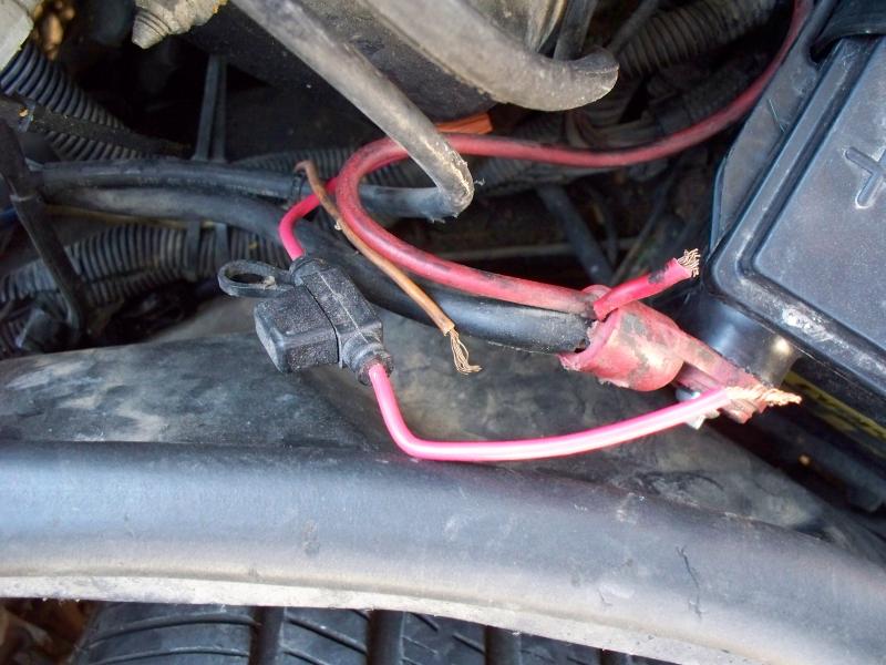
There is a heavy red wire from the battery cable that seems to be intact and runs behind the battery to a junction block that I thought was fuseable link H in the 8A power distribution diagram, but I didn't see the item labled in that diagram "jump start junction block"; is that the junction block I saw behind the battery?
Yesterday I checked all the fuses in the main fuse block and the auxilixary one in the center of the dash and cleaned their contacts. The CTSY/CLK fuse was missing and replacing it turned on the door and under hood lights and made the security light flash with the ignition off. The passenger door light won't turn off so I removed the CTSY/CLK fuse again. I also checked all the lights in the center panel to be sure the check engine light was good and cleaned the contacts of the panel connector.
So...no check engine light with the ignition on and no fuel pump run (pretty obvious why with no B+ to the fuel pump relay). The blower motor runs and the rear hatch release works; I didn't try the headlights yet.
I got to the point in chart A-1 to check the ECM connector for power, but wasn't clear on which terminals were which since the chart numbers and colors did not jive with the colors and letter designations on what I assume is the ECM and its connector with 6 wires.
01-31-2014, 12:02 PM
#15
Intermediate
Thread Starter
Member Since: Jan 2014
Location: Garfield Arkansas
Posts: 36
Likes: 0
Received 0 Likes
on
0 Posts
OK, here are a couple of overall pics of this poor Vette with it's torn seats, cracked top, ripped up carpets, and liberal sprinkling of mouse turds throughout. If I can make it run, it will get vacuumed and washed.
01-31-2014, 01:48 PM
#16
Intermediate
Thread Starter
Member Since: Jan 2014
Location: Garfield Arkansas
Posts: 36
Likes: 0
Received 0 Likes
on
0 Posts
OK, one question down; by the wiring colors this is the cooling fan relay not the fuel pump relay. Not sure why someone was messing with it. I'll get rid of that wire tap and try grounding the green/white wire with the ignition on and see if the fan runs.
01-31-2014, 03:24 PM
#17
Race Director
Member Since: Jan 2003
Location: Summerland B.C. Canada
Posts: 19,667
Likes: 0
Received 36 Likes
on
32 Posts
I have to head back to work,but I will answer a few of your questions.
What you believe is ECM, is the VATS module.
Yes, cooling fan relay should be attached to inner fender.
Yes, that is the junction block where that large red wire goes behind battery.
The door lights are also push on and off, so try pushing the lens to see if goes off.
VATS info is on anther of my web pages.
http://members.shaw.ca/dankai/
I will take more time to answer some more, after work.
01-31-2014, 07:46 PM
#18
Intermediate
Thread Starter
Member Since: Jan 2014
Location: Garfield Arkansas
Posts: 36
Likes: 0
Received 0 Likes
on
0 Posts
I have to head back to work,but I will answer a few of your questions.
What you believe is ECM, is the VATS module.
Yes, cooling fan relay should be attached to inner fender.
Yes, that is the junction block where that large red wire goes behind battery.
The door lights are also push on and off, so try pushing the lens to see if goes off.
VATS info is on anther of my web pages.
http://members.shaw.ca/dankai/
I will take more time to answer some more, after work.
What you believe is ECM, is the VATS module.
Yes, cooling fan relay should be attached to inner fender.
Yes, that is the junction block where that large red wire goes behind battery.
The door lights are also push on and off, so try pushing the lens to see if goes off.
VATS info is on anther of my web pages.
http://members.shaw.ca/dankai/
I will take more time to answer some more, after work.
01-31-2014, 08:04 PM
#19
Race Director
Member Since: Jan 2003
Location: Summerland B.C. Canada
Posts: 19,667
Likes: 0
Received 36 Likes
on
32 Posts
ECM is under the passenger side of dash.
Remove the lower panel with courtesy light, then slide in and look up.
The ECM his held in it's holder with two 10mm screws. Remove them and you can pull the ECM down to work on it.
Remove the lower panel with courtesy light, then slide in and look up.
The ECM his held in it's holder with two 10mm screws. Remove them and you can pull the ECM down to work on it.
01-31-2014, 08:26 PM
#20
Race Director
Member Since: Jan 2003
Location: Summerland B.C. Canada
Posts: 19,667
Likes: 0
Received 36 Likes
on
32 Posts
The white wire in this photo is continuous between the red relay wire and the red wire with the molded fuse holder.
I haven't figured out what the female connector in the corner of that photo, the one with all the wire splices, is for. Could that befor the fuel pump relay?
The other unaccounted for wire is an orange looking one from the big harness; could it be the ECM power?