SOUND DEADENING & STEREO INSTALL (step-by-step):
 01-30-2012, 11:54 PM
#1
Melting Slicks


Thread Starter
I had been planning this install since August, had most of the parts then as well. I started this on Dec. 28, as work was a bit slow and had a lot of time then. To start, create a detailed plan for your install. I’ll be removing the entire interior then adding three deadening layers, a new stereo system, a cell-phone antenna amplifier and a custom-hacked Valentine-One radar detector system. To start I drew a very detailed schematic of all elements <CLICK HERE> … solicited advise from Forum members, then selected and ordered components <CLICK HERE>. Next I created a knock-out list in order of installation <CLICK HERE>. Point is that with proper research, planning and tools you can do anything.
I referenced excellent CorvetteForum (CorFor) threads from KEDAR <CLICK HERE>, TheKOMOMAN <CLICK HERE>, CREASE-GUARD <CLICK HERE>, and Sticky posts on the CorFor/General/ Audio section. I also PM’d and received valuable input from MARKCZ (M-A-N-Y THANKS for all the excellent write-ups and personal advice).
This install is on a 2009 ZHZ 2LT convertible (ZHZ has some options above a standard 2LT). I’m sure I will make some mistakes, typos or misquotes through the post, but everything is stated to the best of my recollection and it all worked-out for me. Just be careful with all the parts so you don’t scrape them, be especially aware of all electrical issues (be sure you know what you’re doing or get help), sharp edges and the use of all tools. I had numerous cuts and scrapes on my hands, as well as scraping up a few pieces ... take your time and be careful. I do not guarantee these steps will work as well for you as they did for me, so follow this advise at your own peril ...
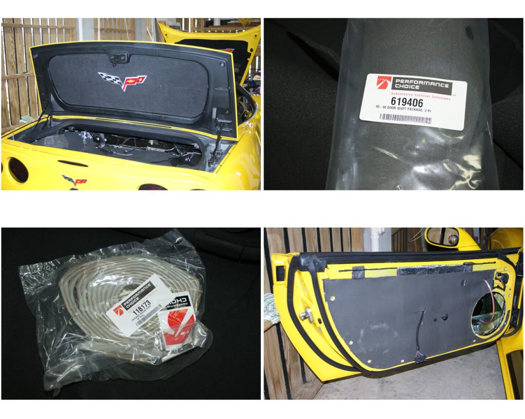
GET ORGANIZED AND PREPARED: Make sure you have all the tools, materials and pieces you’ll need. I laid-out everything on the garage floor and took inventory <CLICK HERE> (then ordered a few other things I was missing). Things to consider: Door-panel popper tool, nylon pry-bars, door-panel replacement pins, epoxies, adhesives & tapes, solvents, speaker wire connectors, zip-lock bags and zip-ties. Set up a couple of tables to put tools and parts on, the bigger the better. Take photos as you remove and install things, as this will prove indispensable when re-installing later (ask me how I know!). Okay, let’s get started:
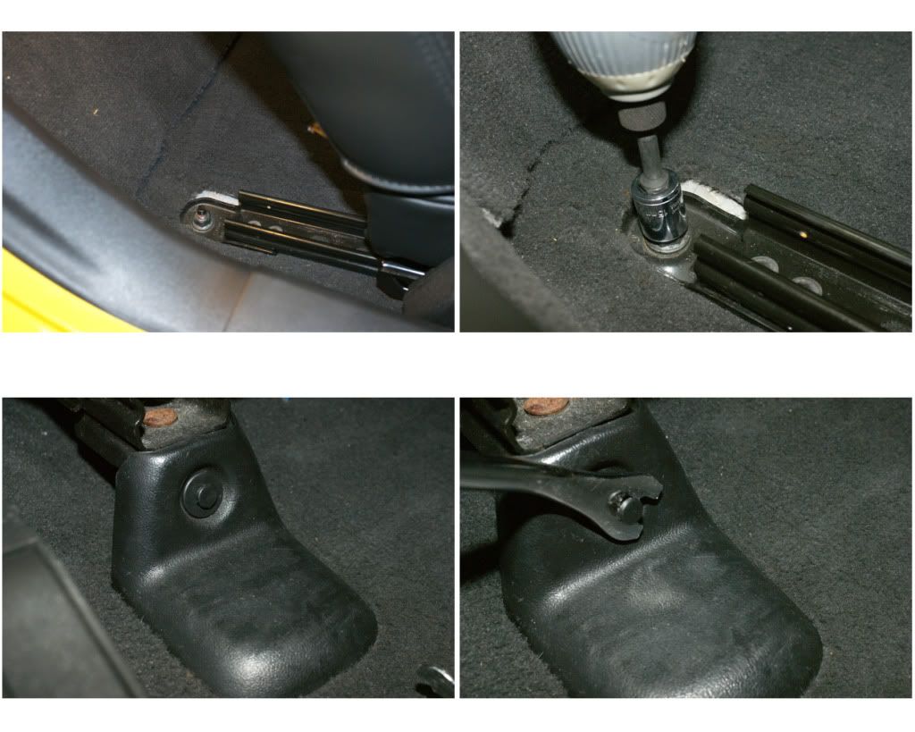
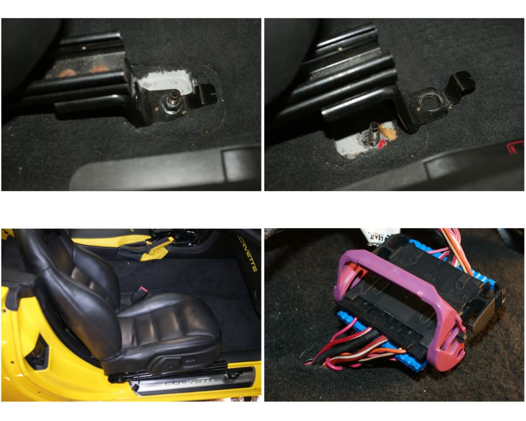
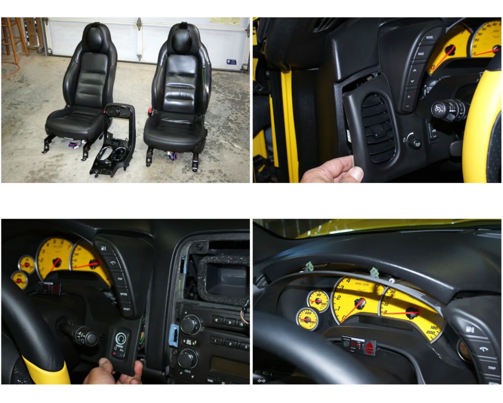
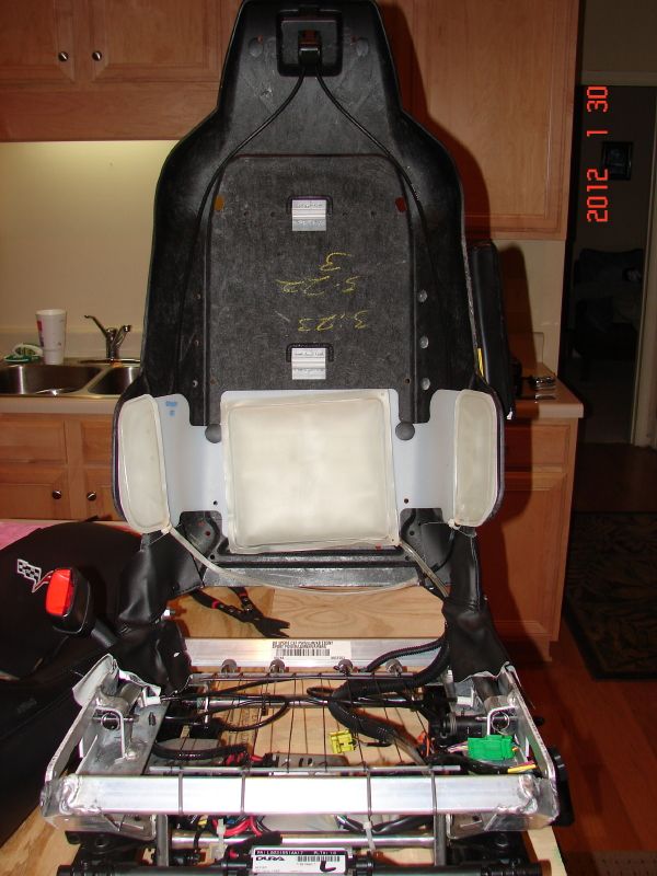
1) REMOVE BOTH SEATS: First, Move seat all the way forward and remove the two rear 15mm nuts. Move seat all the way back, remove the rail-cover push-pins, then the two front nuts. Roll your windows down and disconnect the battery when messing with any airbag item, such as the seats, as we disconnect their electrical plugs. Lift seat and move it slightly forward. Place towel on door sill and pull seat up onto the sill. Lean the seat and unhook the two plugs underneath. On the passenger seat, there’s another plug next to the seat belt bolt, take off the cover (pull-up slot on top over the small metal spade), unbolt the seat-belt and unplug connector. Remove seat. Place nuts and covers in a Zip-Lock bag and label “Passenger Seat” with a black Sharpie. Repeat for driver’s side.

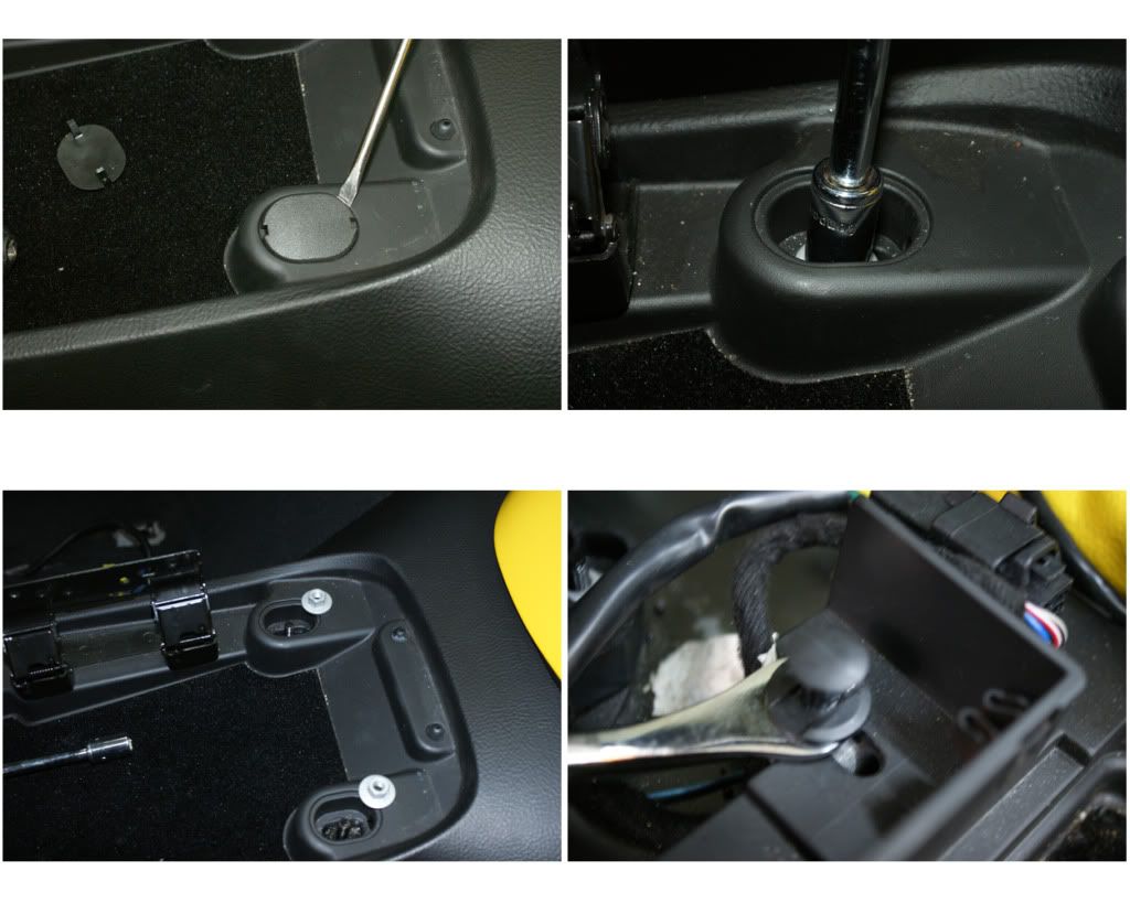
2) CENTER CONSOLE BEZEL: Lift armrest lid and unscrew four T15 screws at hinge and remove lid (put screws in another separately labeled baggy … do this for all parts going forward, you’ll be so glad you did!). Then remove the two front plastic covers and two T15 screws. Unclip the e-brake boot and remove the two 7mm hex-screws for the side bezel. Pull side-bezel down and out, there are two blade-clips to undo at the front, and remove. Put shifter into N, D or S … to lift center bezel off after unplugging. Now pull-up at bottom of center bezel to loosen, then pull-out at top to unclip (there are six blade-clips there).
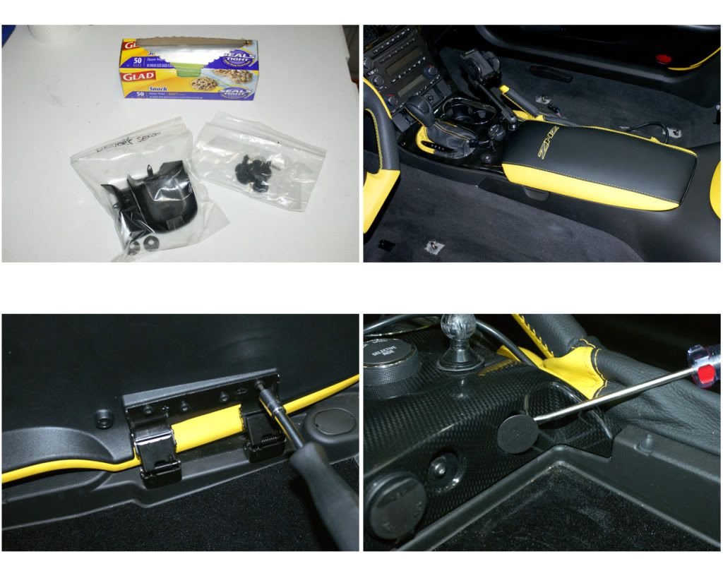
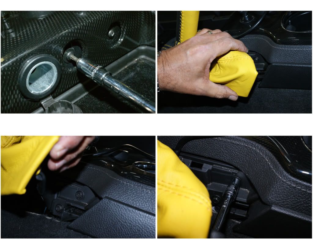
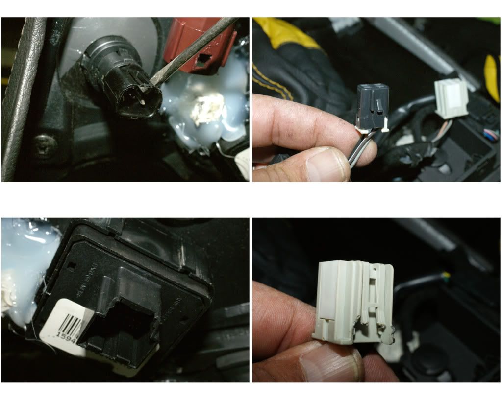
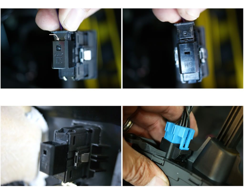
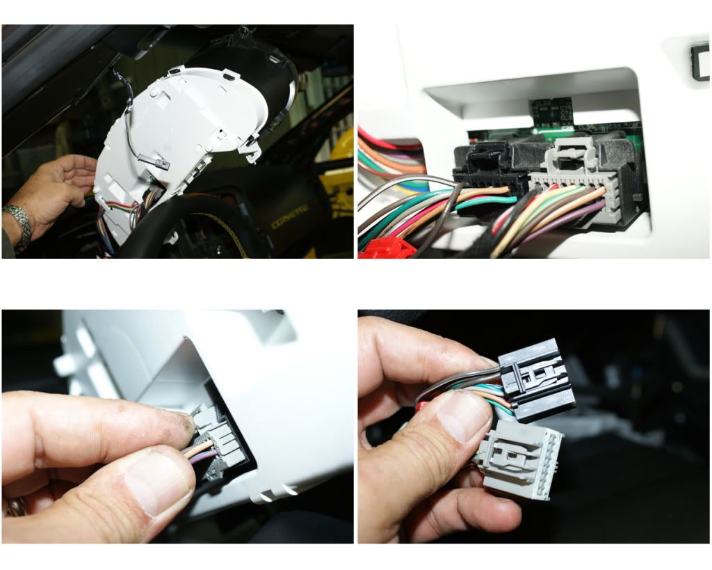
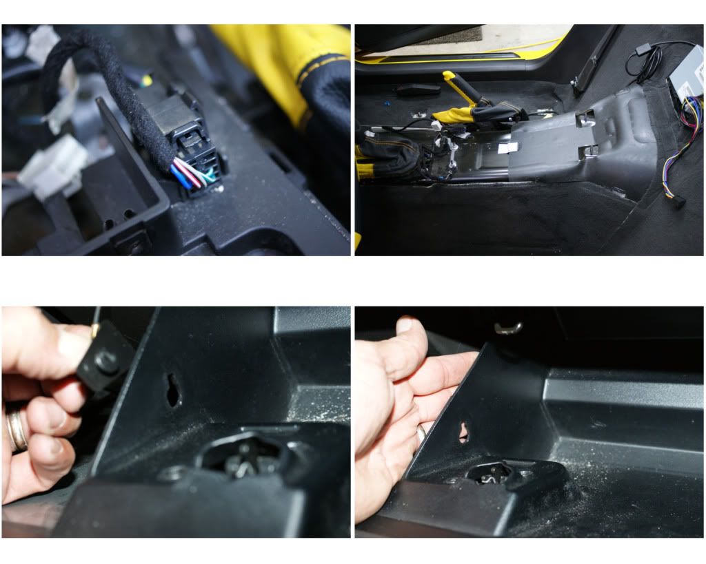
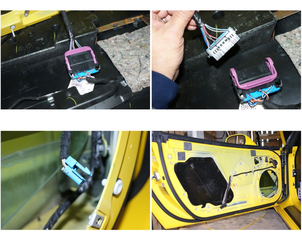
NOW COMES THE MOST DIFFICULT PART OF THIS WHOLE PROJECT … UNPLUGGING THE ELECTRICAL PLUGS!!! Almost all of the plugs have a push-spade or pry-up-spade type of release, so just take your time finding the spades and getting the best angle to press them with a small screwdriver -while pulling the plug to release. Photos will show the receptacle, plug and spade:
1) 12v Power Plug: Press into the small square opening to depress the spade and pull out the plug.
2) Traction Control: Lift-up on the flap from the side with a small screwdriver to raise it above the plug’s fixed tooth -and pull out.
3) Magnetic Ride: My plug-spade was damaged, but appears to be a simple press tab to release.
4) Front Cigarette Lighter: This one is very hard to access, the press-opening is on the far-side, again press into the opening while pulling.
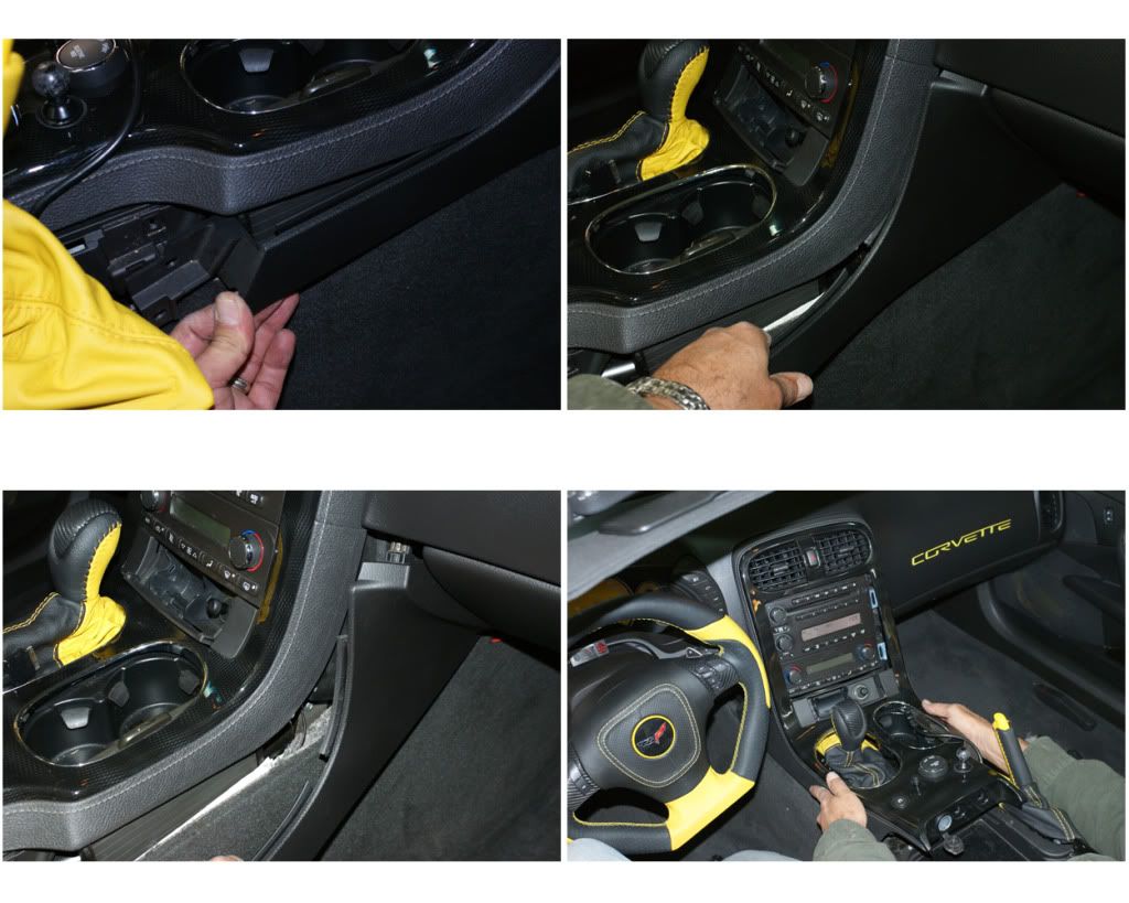
5) Hazard Switch: This one is also tough to access and unhook, it has a press-tab on the bottom. Press it up and pull. --All plugs are now unplugged, lift bezel up and set aside.
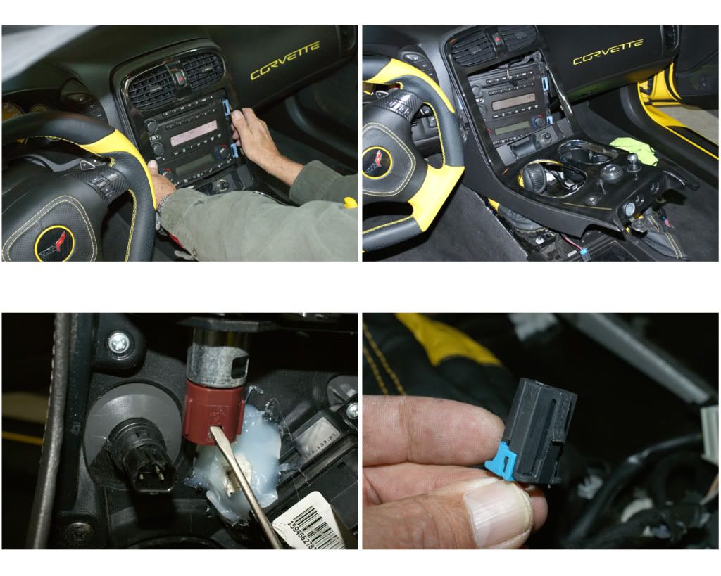
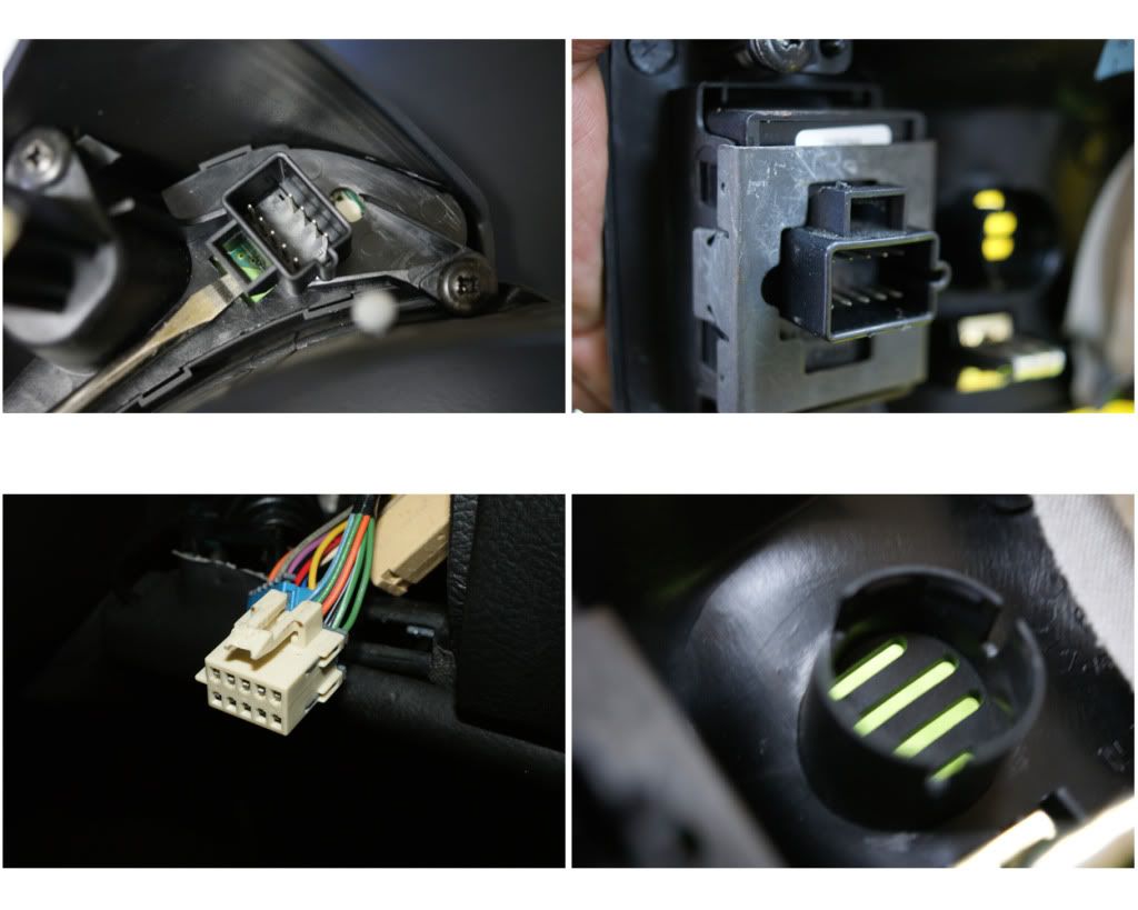
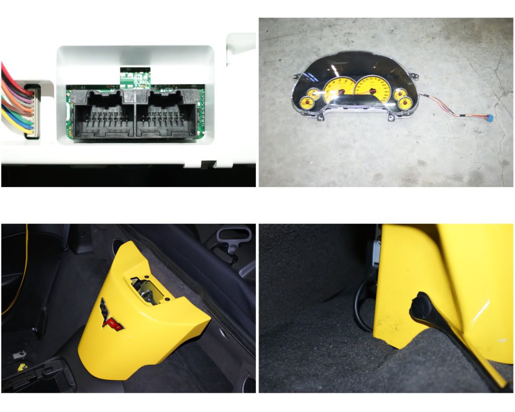
3) GAUGE BEZEL: Removing the bezel & cluster will reveal an open space to mount my Matrix line-driver, allow me to easily route wires and work with the stereo head unit. Start by pulling out on left side, use a pry-bar if necessary. There are four blade-clips here on this side. Then pull out the right side (three blade-clips), and then pull down the top section which has two clips.
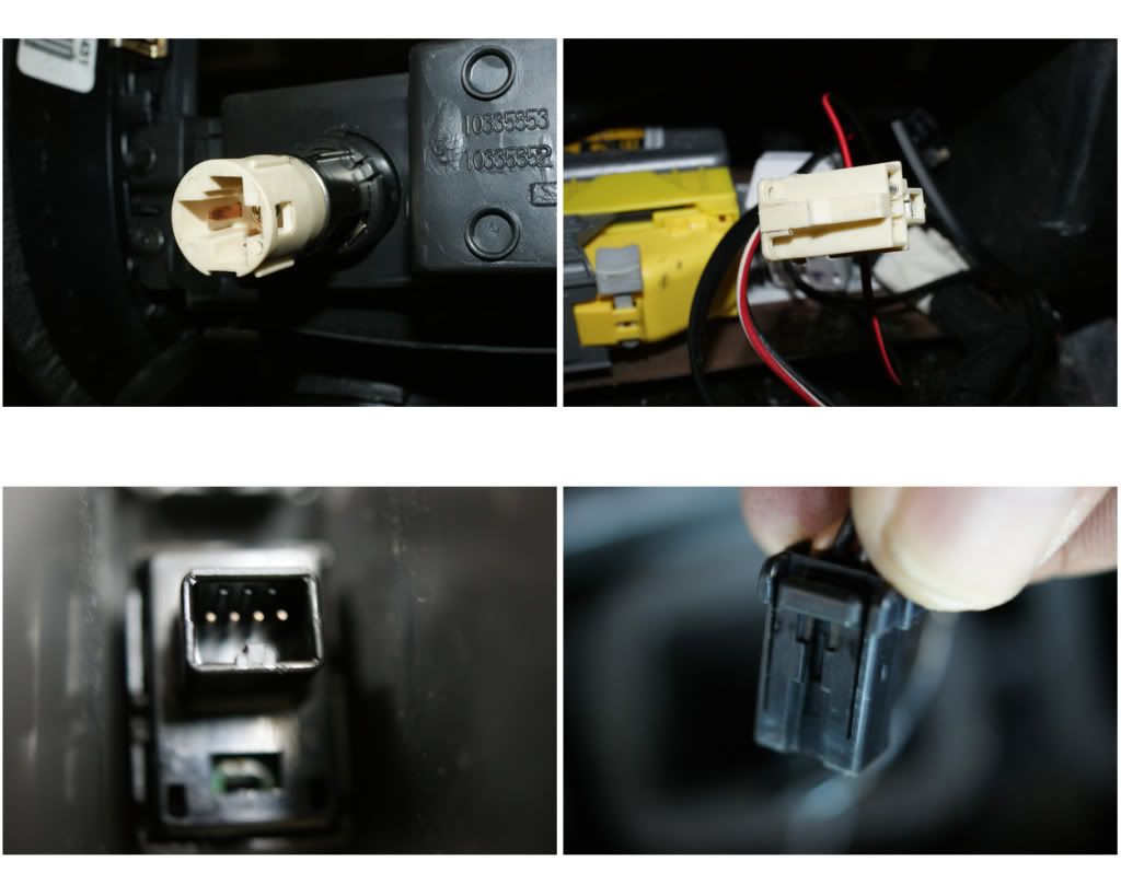
The bezel is now loose and there are six plugs to disconnect, starting from the left, first lower the steering wheel:
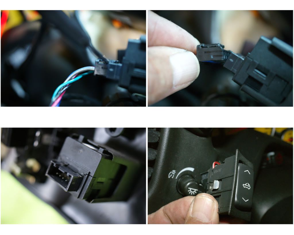
1) Cabin Lights: The clip on top is pried up to release.
2) Power Top: I was able to pull the whole switch out the front, then unplug by prying up under the edge to allow the lock-bump to clear, and pull.
3) HUD Control Pod: This is tough to get to, but the push-spade is on the bottom, push-in and pull (ALT - you could also just remove the 3 screws that hold the switch pod in place with a stubby-screwdriver, for easier access).
4) Ignition: This push-spade is on the top, push & pull.
5) AIR-Sensor: Mine just pulled straight out, but it might need a twist & pull.
6) DIC Control Pod: Same as the other side, spade is on the bottom. --All plugs are now unplugged, lift bezel up, tilt and pull, and set aside.
NOTE: I then reconnected the ignition and power-top switches, so as to be able to use them through the install.
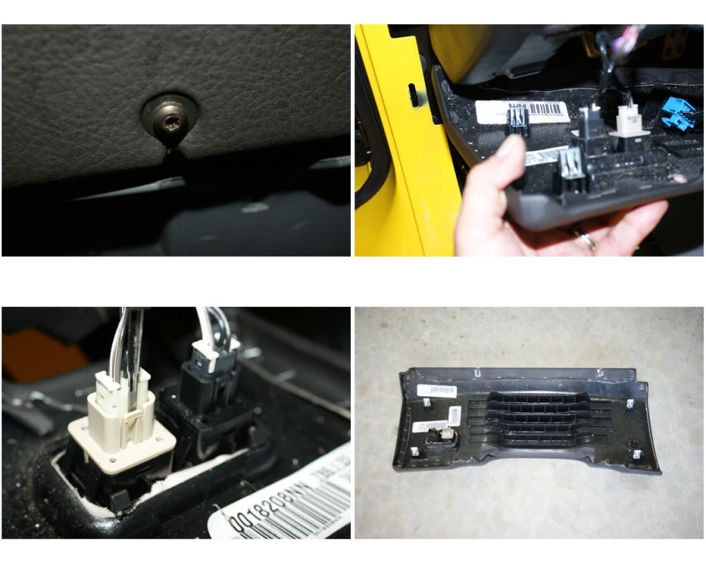
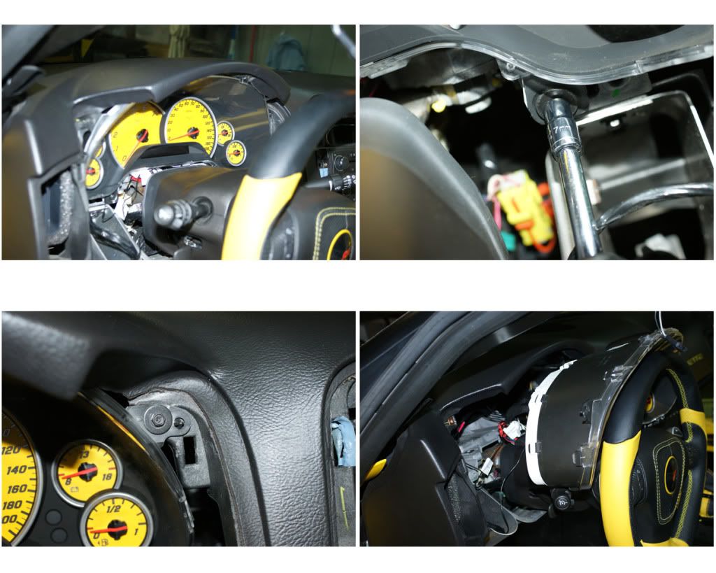
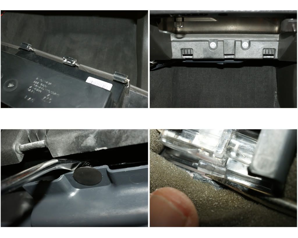
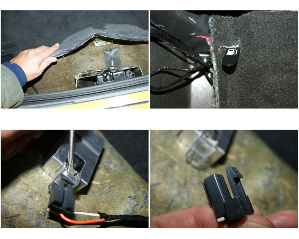
4) GAUGE CLUSTER KNEE BOLSTER: Cluster is held by four 7mm screws at the corners, remove those. Pull and tip cluster down from the top to clear the dash surround, then pull forward onto steering column. Lift up and turn to access two rear plugs and unplug those by pushing down on the lock-spade and pulling. Lift cluster out and set aside. Under the bolster unscrew the two T15 screws, there are two blade-clips on each side so pull panel down and out. Unplug the two plugs (Fuel Door & Trunk) by prying out the lock-tab and pulling. Remove and set aside.
5) WATERFALL: Remove two push pins from the back of the partition and the one on the Lower left side, then the two T15 screws on top, remove and set aside. Mine has the XM-iPod interface (USA-Spec) attached to the back, so I also disconnected that.
6) ARMREST BASE: Pop-up the two back covers and remove the two 10mm nuts. Then remove the front pushpin and pull-out the front relay block from its clips.
7) GLOVE BOX & LOWER COVER: Open box and unhook the left side retainer/damper cord by pushing the cap down and out. Push-in on both the back corners so as the box clears its stops. Box will now swing down. There are three bar-clips on the back, work these free by pulling, twisting and pushing. The lower cover comes off by pulling out the two push pins at the front edge. Then release the light-pod by prying the side clips apart, push the pod down through the opening, turn sideways and pull back up and out. Remove the panel. Repeat same procedure for driver’s side cover.
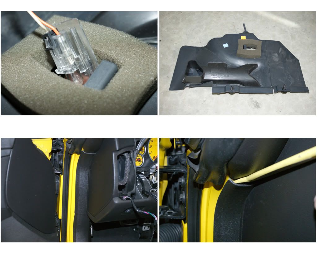
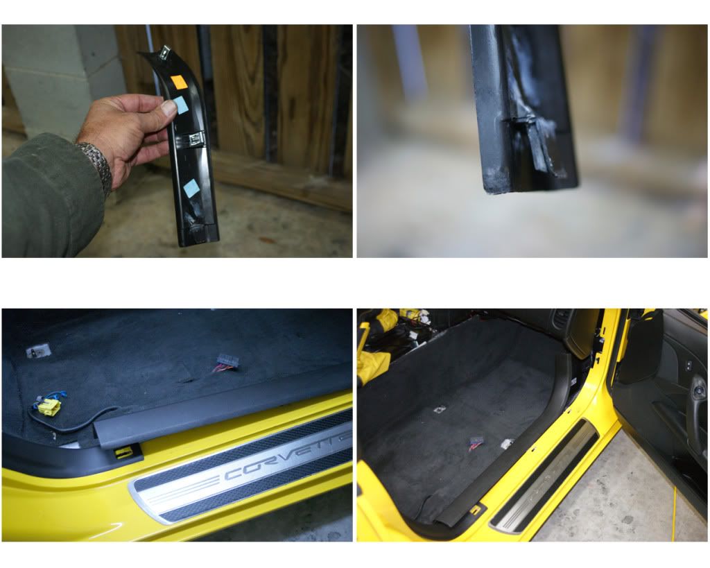
8) DOOR SILL TRIM: Both sides are the same procedure. First remove the small mid-panel that is just below the A-pillar, pry out from the top, releasing the two blade-clips while pulling out and up. There is an “over-clip” at the bottom that slides over the lower trim piece, so be careful not to break this (like I did - epoxy fixed it though), it has to pull up to clear. Next is the door sill piece, pry up the three bottom blade-clips and pull out to release the one front clip. Now the top rear trim piece is removed, pull out the one pushpin and pull forward to release the one blade-clip. I left it with the seat belt through it and pushed it to the side and out of the way. The remaining rear trim piece is held with two blade-clips, pry these out carefully and remove.
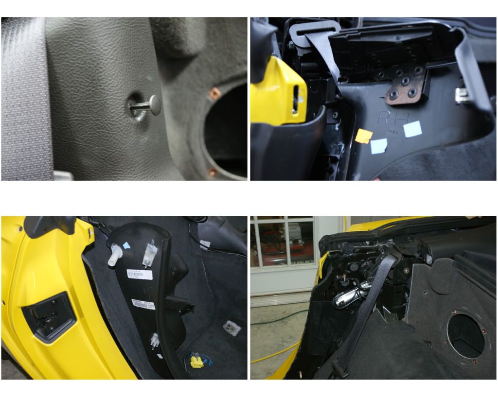
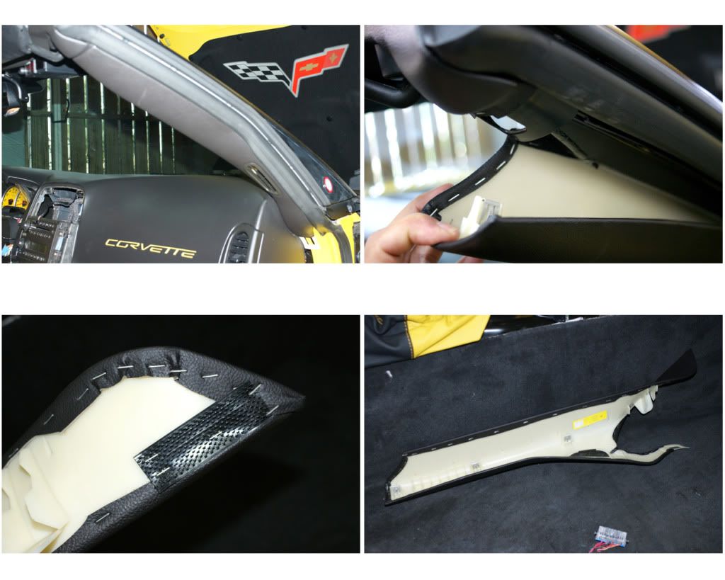
9) PILLAR COVERS: Pry out at the top and pull straight out and slightly toward the inside, there are three blade-clips and a velcro patch at the very bottom-front. On the driver’s side unclip the microphone.
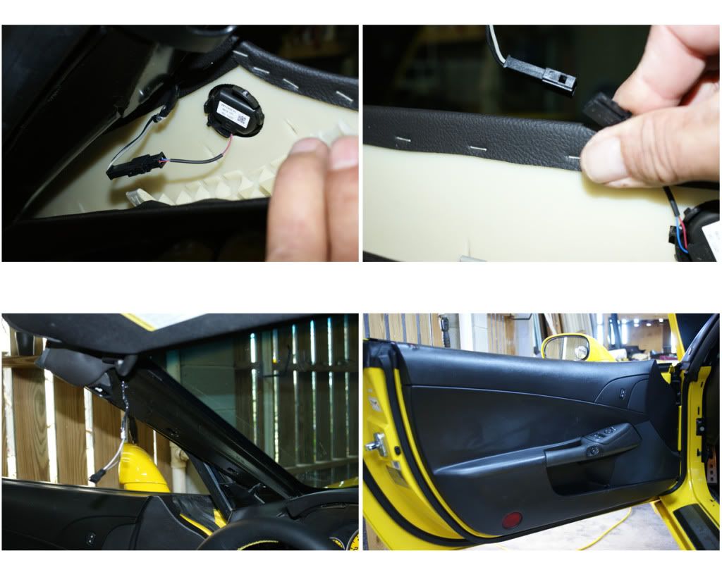
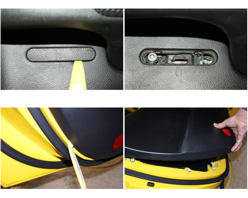
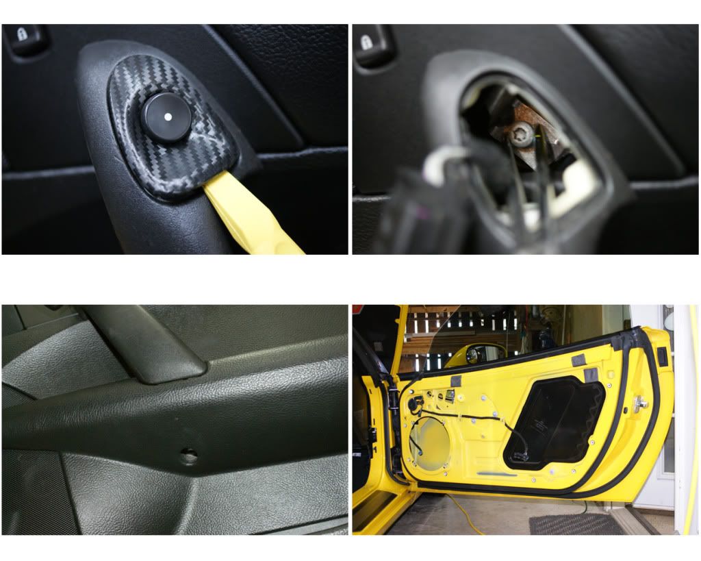
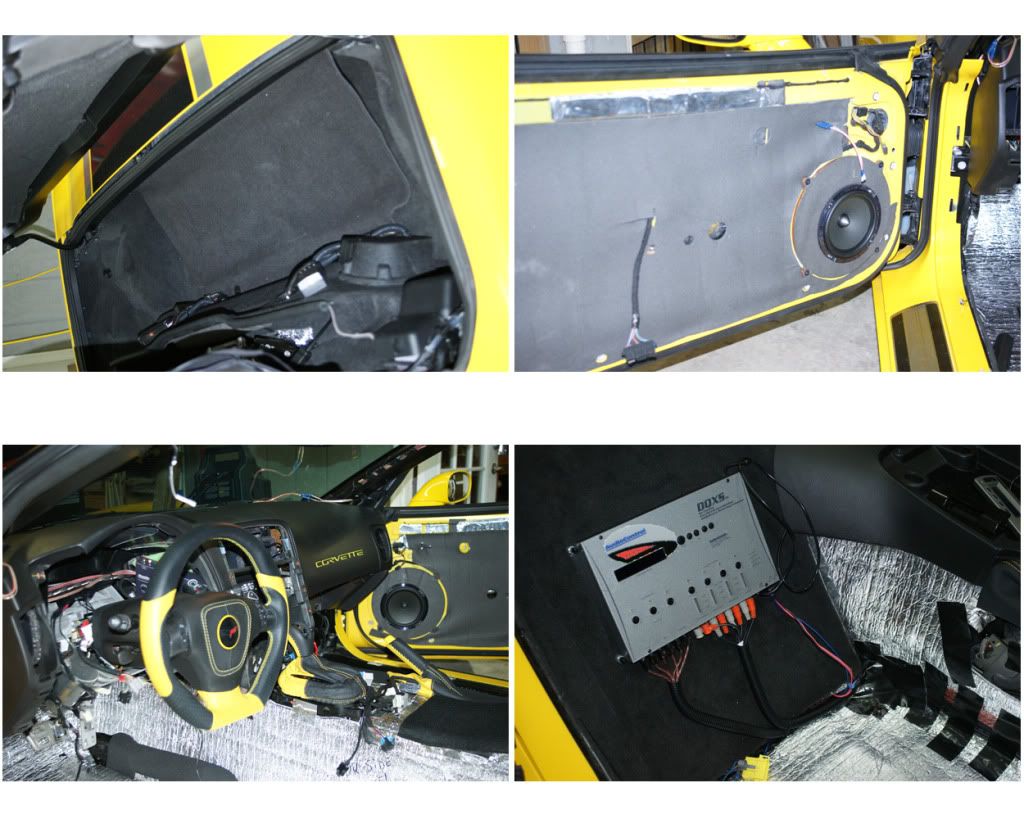
10) DOOR PANELS: Driver’s side; pry out plastic cover just below handle and unscrew the two T30 screws. Pry out bottom back corner of panel bit by bit, get both hands in there and pull out along bottom and sides until whole panel comes loose. Lift panel up and out, keeping a close grip on it, now reach in and unclip the main harness and the speaker plug. Remove panel and set aside. On passenger side there are two separated screws, pry out latch button, leave it dangling then unscrew the T30 screw inside (use hemostats to grab it once loose). The other T30 screw is accessed through the hole below the door handle. It is up and to the back of the hole. If it falls off the bit you can get it when the panel is removed. Pry out and pop all the door pins as before, lift to pull panel out and unhook the harness and speaker.
I am replacing the dented speaker grill on the passenger door (ordered from GM PartsHouse) and sending door panels to be DiNoc'd, to see ALL these photos <CLICK HERE>.
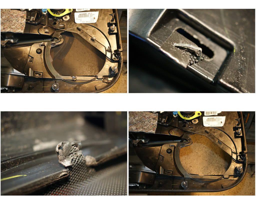
To remove grill, pry out the 10 staples holding the grill tabs down, then bend the tabs up and push grill out (when I put the new one on I used silicon caulk to hold the tabs). I am also covering some of the door’s trim pieces (the two switch plates on each door) covered with 3M Di-Noc, so I need to remove those sections. On the pass-door the lock-switch surround is held by three washer-nuts and a single philips-screw at the bottom right corner. These nuts would not twist-out with needle-nose pliers (maybe you could figure these out), so I broke off the plastic stems and will use small screws to reattach. Snap off the stems and remove the nuts. Next unhook the lock control by prying-out the lock-tab and lifting. Now unscrew the metal handle-brace and straighten the one speaker grill tab coming through the door panel. Then unplug the latch button and push-out panel at top while lifting to clear the door handle tab. Bend the grill tabs up and remove the small grill, then pry out the lock switch. Do the same for the driver-side panel, again there is one screw at the lower left. I also removed both window switch plates.
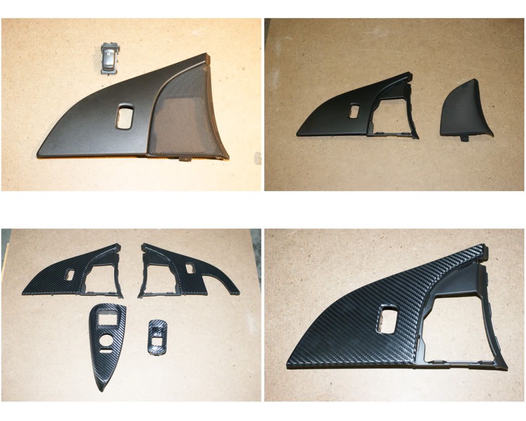
Here they are with the Di-Noc. When reinstalling I used small screws and fender washers, and snapped everything into place. Will leave door panels off until deadening and speaker work is finished.
NOTE: During the install I had to close-up the car each night, as my garage has open slats, but I have WindowValet, so used this to raise and lower the windows w/o the door switches attached. There were several times I had to re-index my windows as well, so to do this I put the drivers door panel just inside the car, connected the door-plug then closed the door to index both windows.
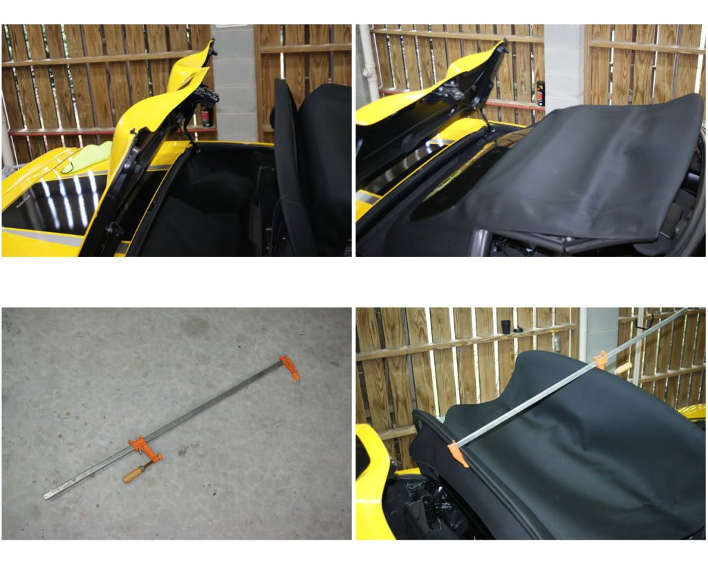
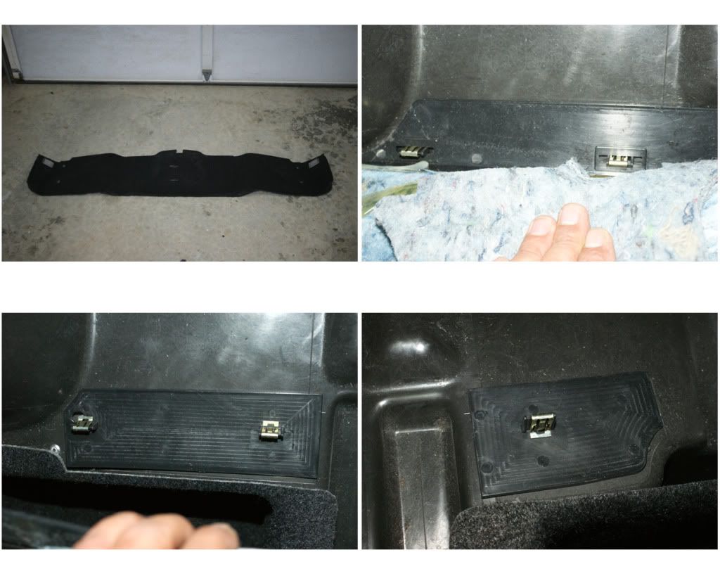
11) PARTITION: With a convertible keeping the tonneau open for work requires use of a bar-clamp, or after a few minutes the fabric top will flop down. Raise or lower top until Tonneau and rear glass are at apex heights, then put the clamp in place to keep the top in position. Inside the folded top storage area is a catch-flap for the top. This connects to the partition base via two snap thingies, pull this up and push away slightly from the partition. Unscrew the two hook-nuts at the partition base, then the two push-pins on either side of upper partition. Disconnect the speaker wires and remove the partition.
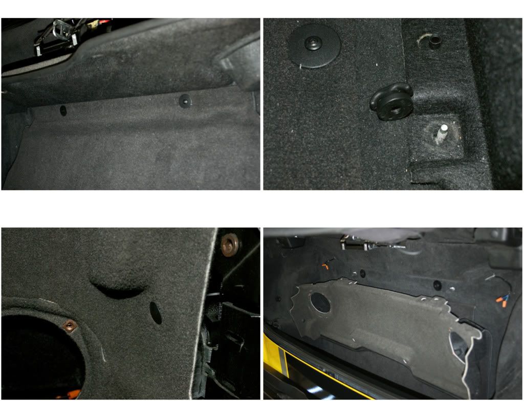
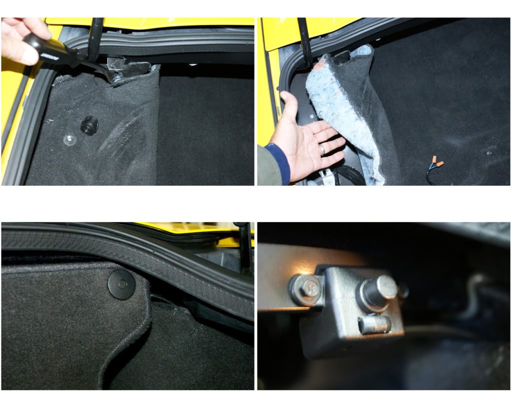
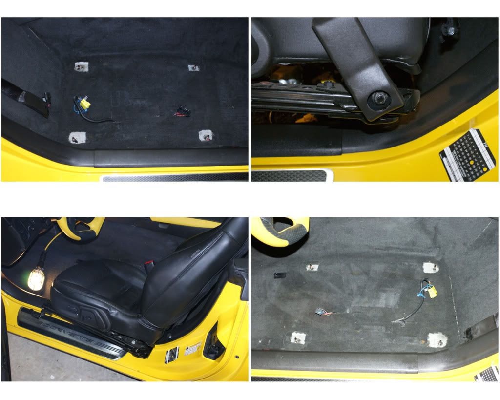
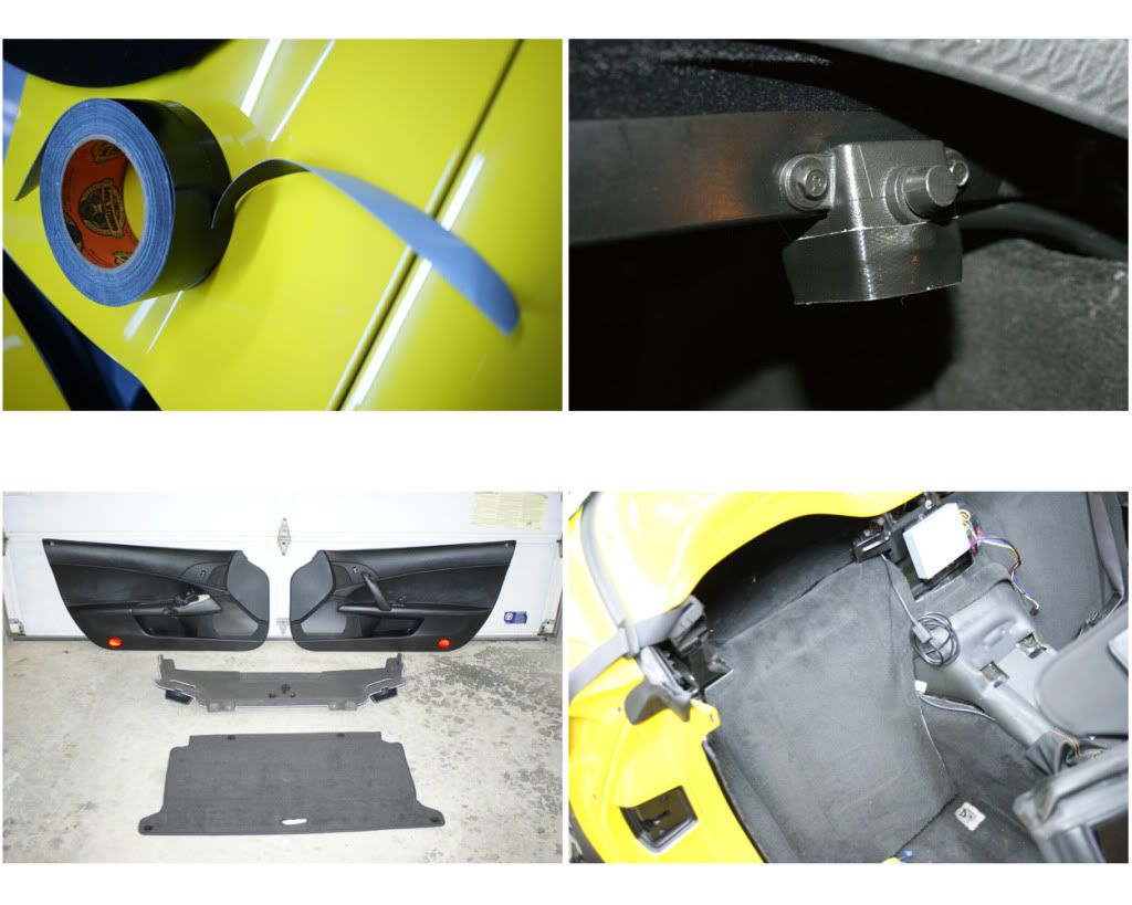
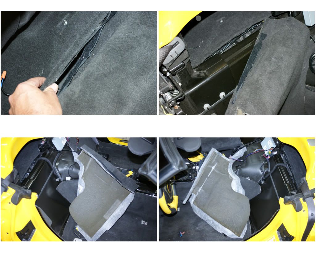
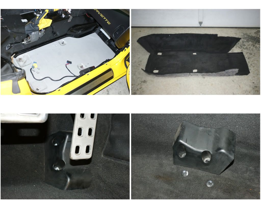
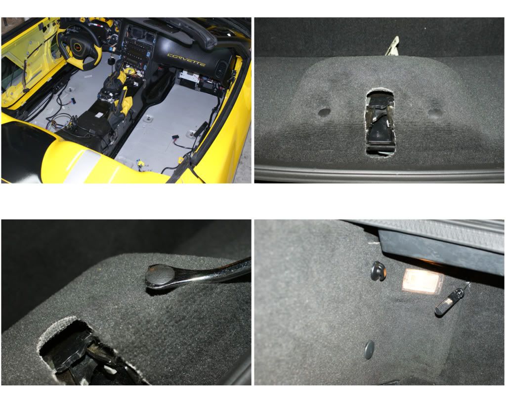
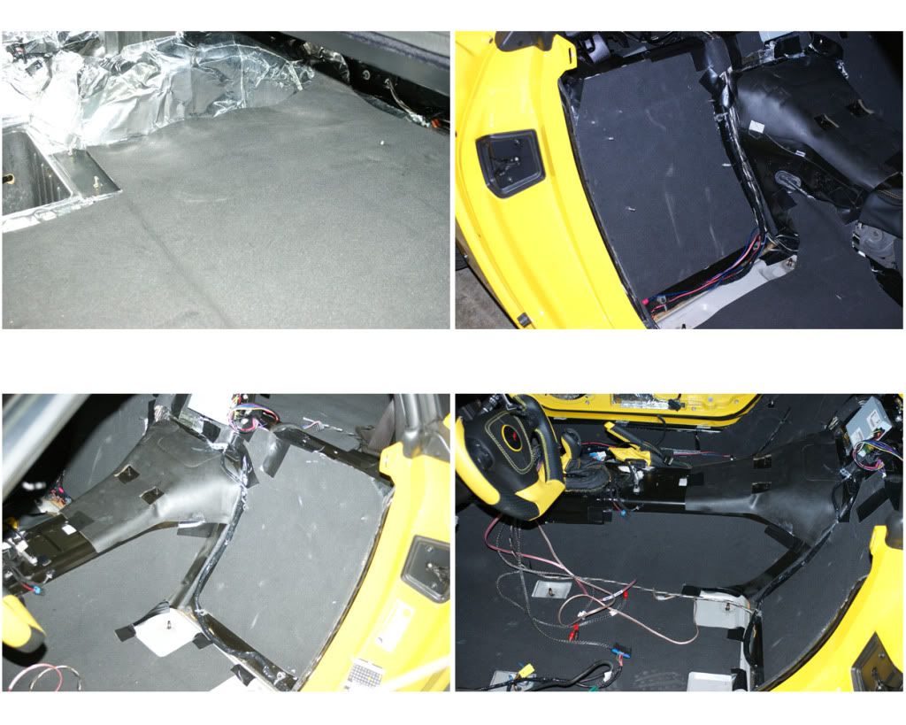
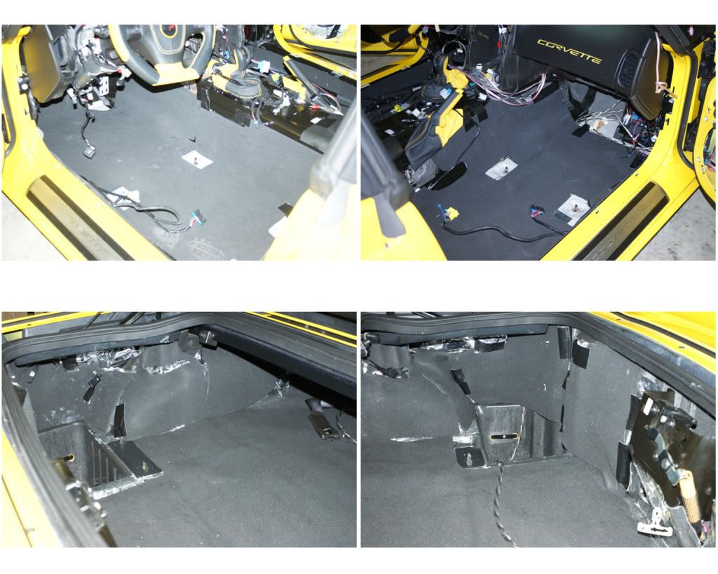
12) CARPET: While in the partition area, unscrew the two hook-nuts on top of the wheel-well, then remove the two push-pins at the top edges. Pull out the carpet areas here on each side, folding it over towards the center so it can be pulled to the rear later. Now remove the bar clamp, raise and secure the vert’s top, and open the trunk. The catch-flap has a security button that makes operating the top and opening the trunk difficult, so I removed the flap and then depressed the switch with a strip of Gorilla Duct Tape wrapped around the module. Close the trunk and lower the top. First carpet to remove is the rear seat wall. At the top it is velcroed to the rear deck carpet, pull this velcro apart, fold over each side and remove that carpet section. To remove the passenger floor carpet first unscrew the lower emergency door latch, pop out the hole covers and unscrew the two long T30 screws. Pull out and up through the carpet slits. Now push the seat connectors through the carpet slits and remove that carpet section. Repeat for driver’s side, but here you must remove the dead pedal and accelerator blocks, each of which uses two 10mm deep-well nuts. Now onto the rear area. First take off the back wall carpet section. There are two push pins to pop-out in the upper center. Then on each side is a screw-hook and a screw-pin to unscrew. Now pull out the carpet from center to the sides, on driver’s side are two emergency releases (door & fuel door) that have to be pushed through carpet slits, and a light on each side -just release their pushpin connects and pull off connector. Remove that rear wall carpet section. For the rear deck carpet pull the carpet from the front area and roll it towards the back. When you get to the cubby holes each cubby frame is secured by blade-clips (two on left & one on the right), pry these up and off, then remove that whole carpet section. I will be installing a subwoofer pod in each of these cubbies, so no deadening in those, so you could just leave the liners in place or not, I removed mine to clean them out.

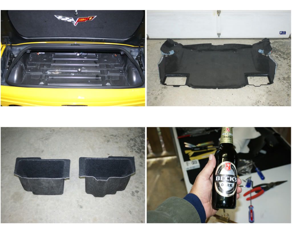
Great job, time for a beverage … we're almost 1/4 done, I'll post more tomorrow ...
I referenced excellent CorvetteForum (CorFor) threads from KEDAR <CLICK HERE>, TheKOMOMAN <CLICK HERE>, CREASE-GUARD <CLICK HERE>, and Sticky posts on the CorFor/General/ Audio section. I also PM’d and received valuable input from MARKCZ (M-A-N-Y THANKS for all the excellent write-ups and personal advice).
This install is on a 2009 ZHZ 2LT convertible (ZHZ has some options above a standard 2LT). I’m sure I will make some mistakes, typos or misquotes through the post, but everything is stated to the best of my recollection and it all worked-out for me. Just be careful with all the parts so you don’t scrape them, be especially aware of all electrical issues (be sure you know what you’re doing or get help), sharp edges and the use of all tools. I had numerous cuts and scrapes on my hands, as well as scraping up a few pieces ... take your time and be careful. I do not guarantee these steps will work as well for you as they did for me, so follow this advise at your own peril ...
GET ORGANIZED AND PREPARED: Make sure you have all the tools, materials and pieces you’ll need. I laid-out everything on the garage floor and took inventory <CLICK HERE> (then ordered a few other things I was missing). Things to consider: Door-panel popper tool, nylon pry-bars, door-panel replacement pins, epoxies, adhesives & tapes, solvents, speaker wire connectors, zip-lock bags and zip-ties. Set up a couple of tables to put tools and parts on, the bigger the better. Take photos as you remove and install things, as this will prove indispensable when re-installing later (ask me how I know!). Okay, let’s get started:
1) REMOVE BOTH SEATS: First, Move seat all the way forward and remove the two rear 15mm nuts. Move seat all the way back, remove the rail-cover push-pins, then the two front nuts. Roll your windows down and disconnect the battery when messing with any airbag item, such as the seats, as we disconnect their electrical plugs. Lift seat and move it slightly forward. Place towel on door sill and pull seat up onto the sill. Lean the seat and unhook the two plugs underneath. On the passenger seat, there’s another plug next to the seat belt bolt, take off the cover (pull-up slot on top over the small metal spade), unbolt the seat-belt and unplug connector. Remove seat. Place nuts and covers in a Zip-Lock bag and label “Passenger Seat” with a black Sharpie. Repeat for driver’s side.
2) CENTER CONSOLE BEZEL: Lift armrest lid and unscrew four T15 screws at hinge and remove lid (put screws in another separately labeled baggy … do this for all parts going forward, you’ll be so glad you did!). Then remove the two front plastic covers and two T15 screws. Unclip the e-brake boot and remove the two 7mm hex-screws for the side bezel. Pull side-bezel down and out, there are two blade-clips to undo at the front, and remove. Put shifter into N, D or S … to lift center bezel off after unplugging. Now pull-up at bottom of center bezel to loosen, then pull-out at top to unclip (there are six blade-clips there).
NOW COMES THE MOST DIFFICULT PART OF THIS WHOLE PROJECT … UNPLUGGING THE ELECTRICAL PLUGS!!! Almost all of the plugs have a push-spade or pry-up-spade type of release, so just take your time finding the spades and getting the best angle to press them with a small screwdriver -while pulling the plug to release. Photos will show the receptacle, plug and spade:
1) 12v Power Plug: Press into the small square opening to depress the spade and pull out the plug.
2) Traction Control: Lift-up on the flap from the side with a small screwdriver to raise it above the plug’s fixed tooth -and pull out.
3) Magnetic Ride: My plug-spade was damaged, but appears to be a simple press tab to release.
4) Front Cigarette Lighter: This one is very hard to access, the press-opening is on the far-side, again press into the opening while pulling.
5) Hazard Switch: This one is also tough to access and unhook, it has a press-tab on the bottom. Press it up and pull. --All plugs are now unplugged, lift bezel up and set aside.
3) GAUGE BEZEL: Removing the bezel & cluster will reveal an open space to mount my Matrix line-driver, allow me to easily route wires and work with the stereo head unit. Start by pulling out on left side, use a pry-bar if necessary. There are four blade-clips here on this side. Then pull out the right side (three blade-clips), and then pull down the top section which has two clips.
The bezel is now loose and there are six plugs to disconnect, starting from the left, first lower the steering wheel:
1) Cabin Lights: The clip on top is pried up to release.
2) Power Top: I was able to pull the whole switch out the front, then unplug by prying up under the edge to allow the lock-bump to clear, and pull.
3) HUD Control Pod: This is tough to get to, but the push-spade is on the bottom, push-in and pull (ALT - you could also just remove the 3 screws that hold the switch pod in place with a stubby-screwdriver, for easier access).
4) Ignition: This push-spade is on the top, push & pull.
5) AIR-Sensor: Mine just pulled straight out, but it might need a twist & pull.
6) DIC Control Pod: Same as the other side, spade is on the bottom. --All plugs are now unplugged, lift bezel up, tilt and pull, and set aside.
NOTE: I then reconnected the ignition and power-top switches, so as to be able to use them through the install.
4) GAUGE CLUSTER KNEE BOLSTER: Cluster is held by four 7mm screws at the corners, remove those. Pull and tip cluster down from the top to clear the dash surround, then pull forward onto steering column. Lift up and turn to access two rear plugs and unplug those by pushing down on the lock-spade and pulling. Lift cluster out and set aside. Under the bolster unscrew the two T15 screws, there are two blade-clips on each side so pull panel down and out. Unplug the two plugs (Fuel Door & Trunk) by prying out the lock-tab and pulling. Remove and set aside.
5) WATERFALL: Remove two push pins from the back of the partition and the one on the Lower left side, then the two T15 screws on top, remove and set aside. Mine has the XM-iPod interface (USA-Spec) attached to the back, so I also disconnected that.
6) ARMREST BASE: Pop-up the two back covers and remove the two 10mm nuts. Then remove the front pushpin and pull-out the front relay block from its clips.
7) GLOVE BOX & LOWER COVER: Open box and unhook the left side retainer/damper cord by pushing the cap down and out. Push-in on both the back corners so as the box clears its stops. Box will now swing down. There are three bar-clips on the back, work these free by pulling, twisting and pushing. The lower cover comes off by pulling out the two push pins at the front edge. Then release the light-pod by prying the side clips apart, push the pod down through the opening, turn sideways and pull back up and out. Remove the panel. Repeat same procedure for driver’s side cover.
8) DOOR SILL TRIM: Both sides are the same procedure. First remove the small mid-panel that is just below the A-pillar, pry out from the top, releasing the two blade-clips while pulling out and up. There is an “over-clip” at the bottom that slides over the lower trim piece, so be careful not to break this (like I did - epoxy fixed it though), it has to pull up to clear. Next is the door sill piece, pry up the three bottom blade-clips and pull out to release the one front clip. Now the top rear trim piece is removed, pull out the one pushpin and pull forward to release the one blade-clip. I left it with the seat belt through it and pushed it to the side and out of the way. The remaining rear trim piece is held with two blade-clips, pry these out carefully and remove.
9) PILLAR COVERS: Pry out at the top and pull straight out and slightly toward the inside, there are three blade-clips and a velcro patch at the very bottom-front. On the driver’s side unclip the microphone.
10) DOOR PANELS: Driver’s side; pry out plastic cover just below handle and unscrew the two T30 screws. Pry out bottom back corner of panel bit by bit, get both hands in there and pull out along bottom and sides until whole panel comes loose. Lift panel up and out, keeping a close grip on it, now reach in and unclip the main harness and the speaker plug. Remove panel and set aside. On passenger side there are two separated screws, pry out latch button, leave it dangling then unscrew the T30 screw inside (use hemostats to grab it once loose). The other T30 screw is accessed through the hole below the door handle. It is up and to the back of the hole. If it falls off the bit you can get it when the panel is removed. Pry out and pop all the door pins as before, lift to pull panel out and unhook the harness and speaker.
I am replacing the dented speaker grill on the passenger door (ordered from GM PartsHouse) and sending door panels to be DiNoc'd, to see ALL these photos <CLICK HERE>.
To remove grill, pry out the 10 staples holding the grill tabs down, then bend the tabs up and push grill out (when I put the new one on I used silicon caulk to hold the tabs). I am also covering some of the door’s trim pieces (the two switch plates on each door) covered with 3M Di-Noc, so I need to remove those sections. On the pass-door the lock-switch surround is held by three washer-nuts and a single philips-screw at the bottom right corner. These nuts would not twist-out with needle-nose pliers (maybe you could figure these out), so I broke off the plastic stems and will use small screws to reattach. Snap off the stems and remove the nuts. Next unhook the lock control by prying-out the lock-tab and lifting. Now unscrew the metal handle-brace and straighten the one speaker grill tab coming through the door panel. Then unplug the latch button and push-out panel at top while lifting to clear the door handle tab. Bend the grill tabs up and remove the small grill, then pry out the lock switch. Do the same for the driver-side panel, again there is one screw at the lower left. I also removed both window switch plates.
Here they are with the Di-Noc. When reinstalling I used small screws and fender washers, and snapped everything into place. Will leave door panels off until deadening and speaker work is finished.
NOTE: During the install I had to close-up the car each night, as my garage has open slats, but I have WindowValet, so used this to raise and lower the windows w/o the door switches attached. There were several times I had to re-index my windows as well, so to do this I put the drivers door panel just inside the car, connected the door-plug then closed the door to index both windows.
11) PARTITION: With a convertible keeping the tonneau open for work requires use of a bar-clamp, or after a few minutes the fabric top will flop down. Raise or lower top until Tonneau and rear glass are at apex heights, then put the clamp in place to keep the top in position. Inside the folded top storage area is a catch-flap for the top. This connects to the partition base via two snap thingies, pull this up and push away slightly from the partition. Unscrew the two hook-nuts at the partition base, then the two push-pins on either side of upper partition. Disconnect the speaker wires and remove the partition.
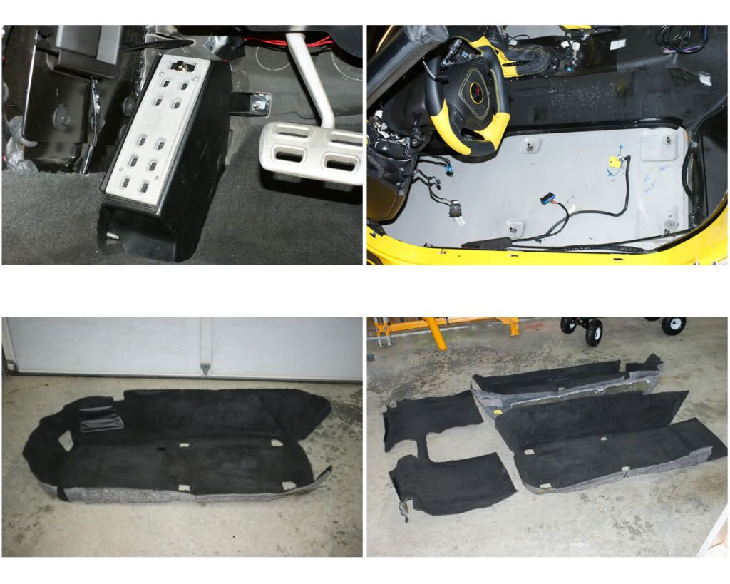
12) CARPET: While in the partition area, unscrew the two hook-nuts on top of the wheel-well, then remove the two push-pins at the top edges. Pull out the carpet areas here on each side, folding it over towards the center so it can be pulled to the rear later. Now remove the bar clamp, raise and secure the vert’s top, and open the trunk. The catch-flap has a security button that makes operating the top and opening the trunk difficult, so I removed the flap and then depressed the switch with a strip of Gorilla Duct Tape wrapped around the module. Close the trunk and lower the top. First carpet to remove is the rear seat wall. At the top it is velcroed to the rear deck carpet, pull this velcro apart, fold over each side and remove that carpet section. To remove the passenger floor carpet first unscrew the lower emergency door latch, pop out the hole covers and unscrew the two long T30 screws. Pull out and up through the carpet slits. Now push the seat connectors through the carpet slits and remove that carpet section. Repeat for driver’s side, but here you must remove the dead pedal and accelerator blocks, each of which uses two 10mm deep-well nuts. Now onto the rear area. First take off the back wall carpet section. There are two push pins to pop-out in the upper center. Then on each side is a screw-hook and a screw-pin to unscrew. Now pull out the carpet from center to the sides, on driver’s side are two emergency releases (door & fuel door) that have to be pushed through carpet slits, and a light on each side -just release their pushpin connects and pull off connector. Remove that rear wall carpet section. For the rear deck carpet pull the carpet from the front area and roll it towards the back. When you get to the cubby holes each cubby frame is secured by blade-clips (two on left & one on the right), pry these up and off, then remove that whole carpet section. I will be installing a subwoofer pod in each of these cubbies, so no deadening in those, so you could just leave the liners in place or not, I removed mine to clean them out.
Great job, time for a beverage … we're almost 1/4 done, I'll post more tomorrow ...
Last edited by Thrash; 03-26-2012 at 06:54 PM.

The following 3 users liked this post by Thrash:
01-31-2012, 01:15 AM
#2
Tech Contributor


GREAT photos, Bill. 
I just removed everything like you have done and my car is in the shop getting the ZR1 front end conversion right now.
When I get it back I will be doing a complete audio upgrade also. I am looking forward to seeing what you do.
It may help me do my installation better.
Thanks!
Subscribed
Just to pass the time while I am waiting on my car, I'm changing out the seats to the 2012 style.
Last edited by ncvette_1FUNRIDE; 01-31-2012 at 01:24 AM.
01-31-2012, 04:16 PM
#4
Tech Contributor
I never seem to be able to take pics along the way. I'll start out OK, but the usually get into a groove and completely forget about the pics. You definitely don't seem to have that problem.
What steering wheel is this?
What steering wheel is this?
 01-31-2012, 08:06 PM
#7
Le Mans Master

Member Since: Mar 2005
Location: Rocklin California
Posts: 7,631
Likes: 0
Received 11 Likes
on
11 Posts
Very nice pics and write-up. 90% of the issues new owners have is with the disassembly and re-assembly of all the trim when installing stereo components. Clips and pins and connectors are a nightmare. We don't want to break all those expensive plastic parts. Great job!
01-31-2012, 10:16 PM
#8
Drifting

Amazing write up and execution, can't wait to see it through the home stretch!
Good job and thanks for sharing!
Good job and thanks for sharing!
01-31-2012, 11:19 PM
#9
Melting Slicks
Thread Starter
PART TWO: "To infinity and beyond" ...
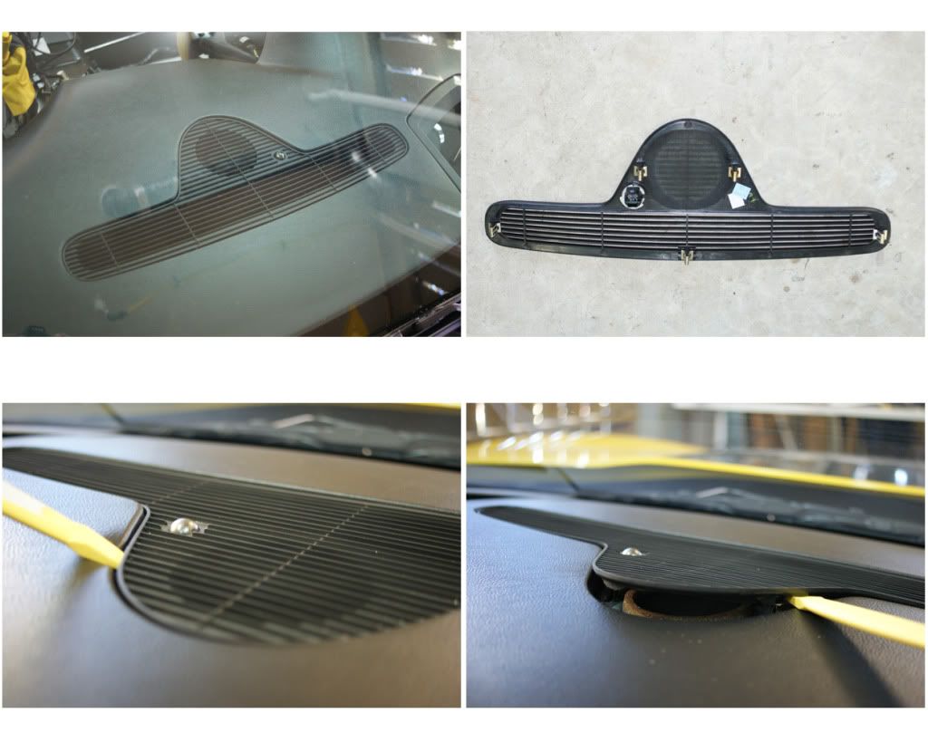
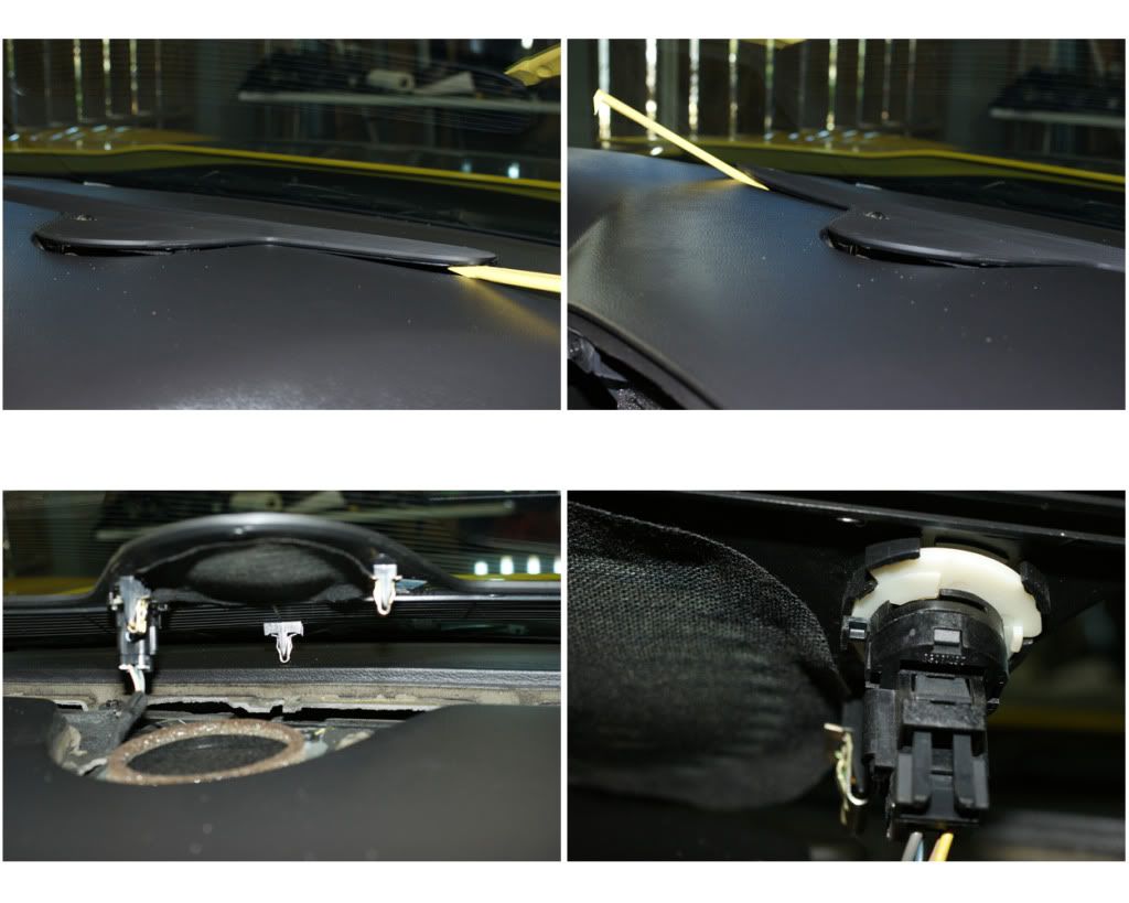
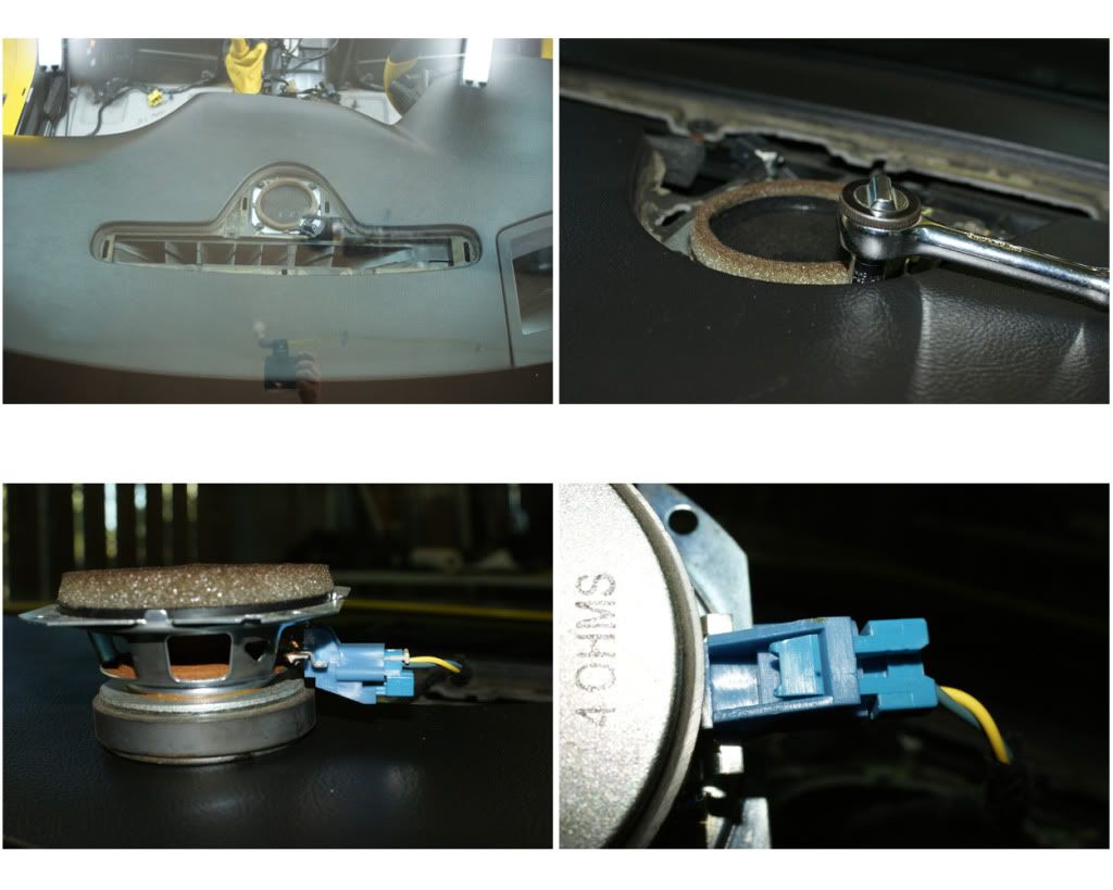
13) KILLING CENTER SPEAKER: Two clips are on either side of circular area, pry up on each side, then pry up the two clips on the longer ends, and there’s one last clip in middle rear. Unclip light sensor’s push-spade and remove. Speaker in held by four 7mm screws, remove speaker, disconnect and reinstall -or remove entirely (I left it in place).
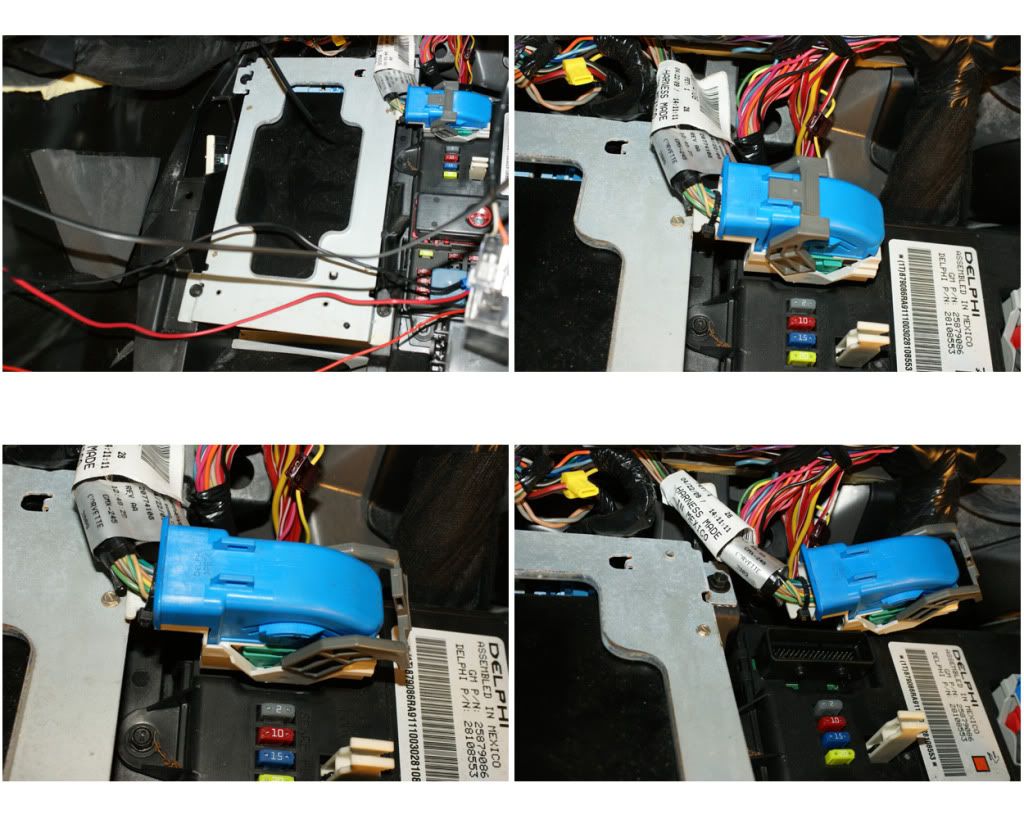
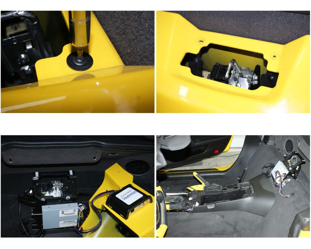
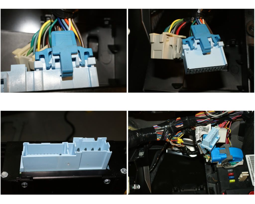
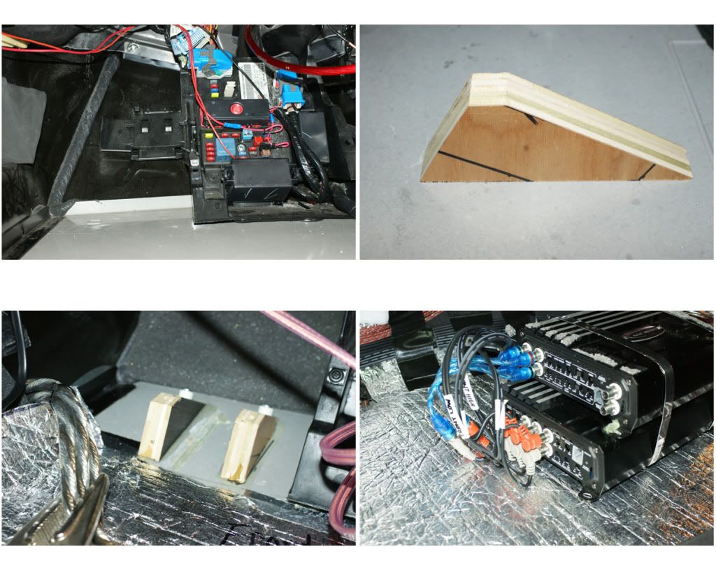
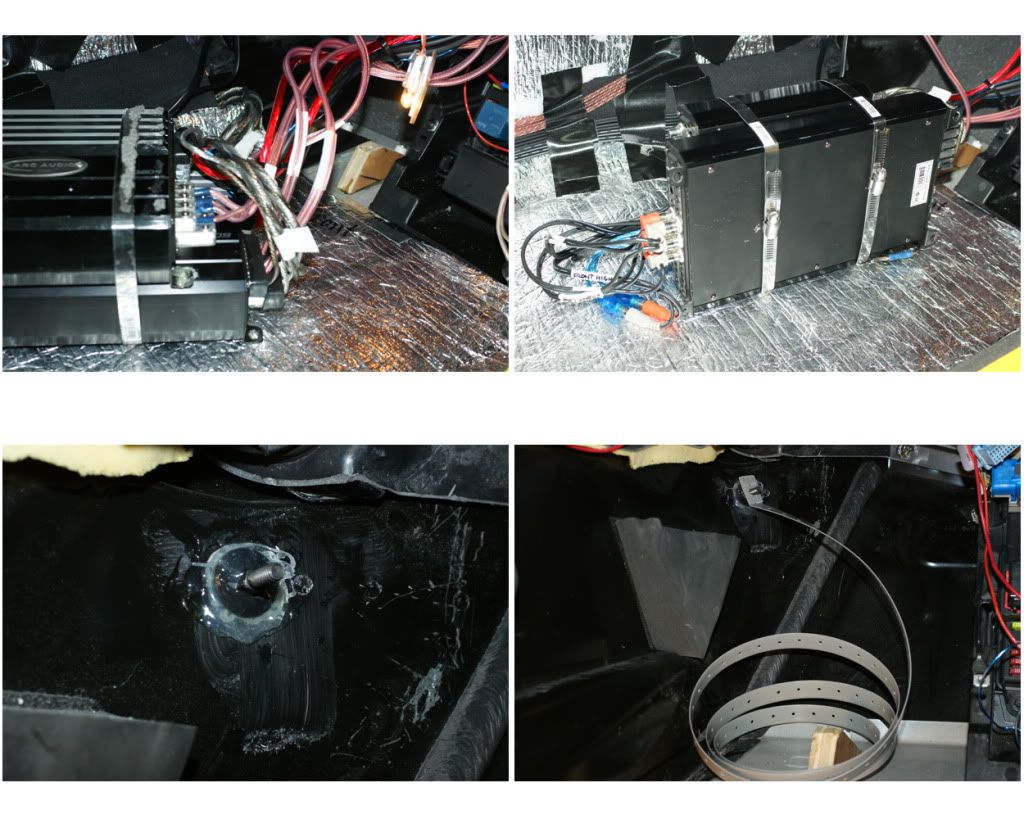
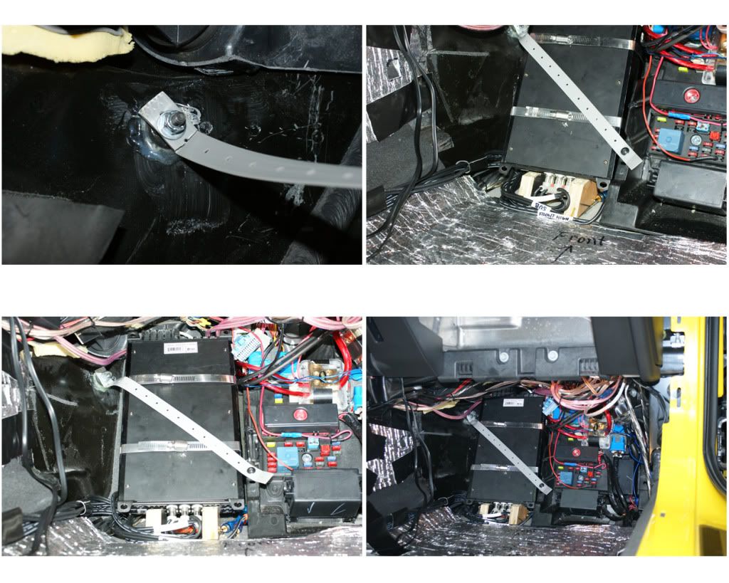
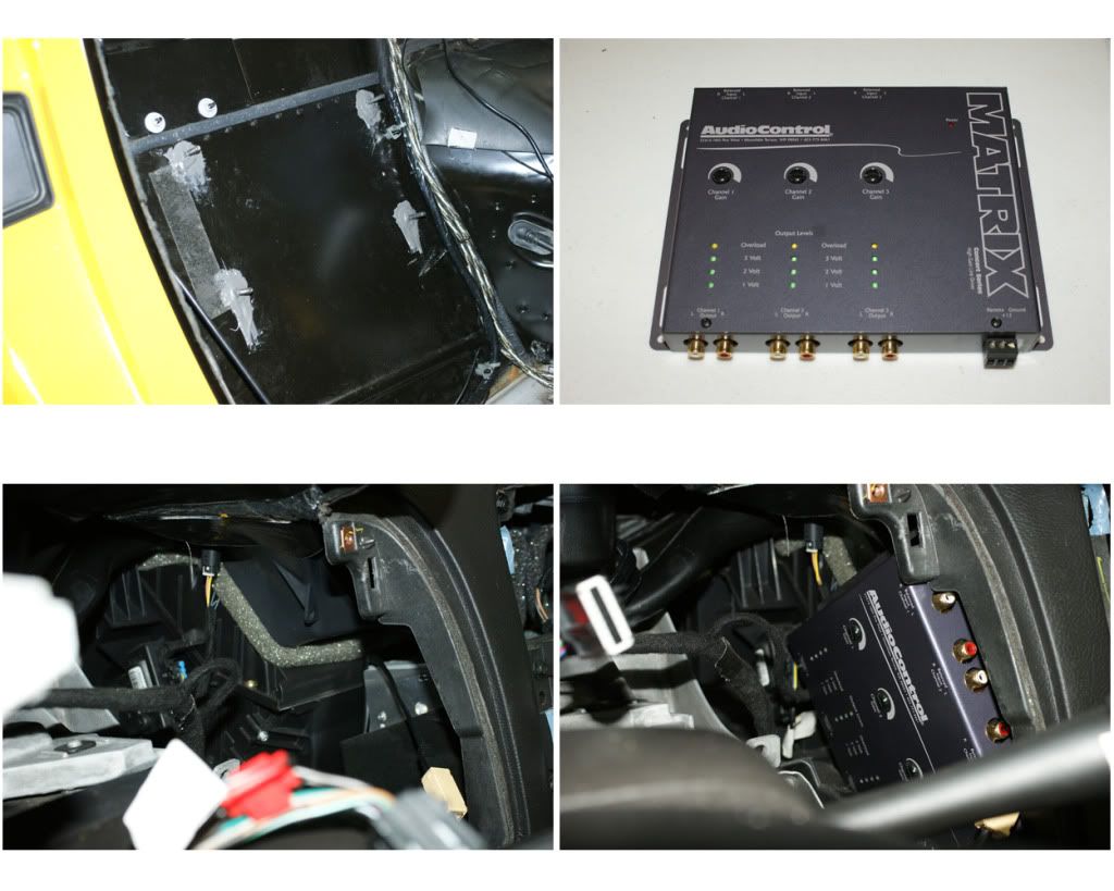
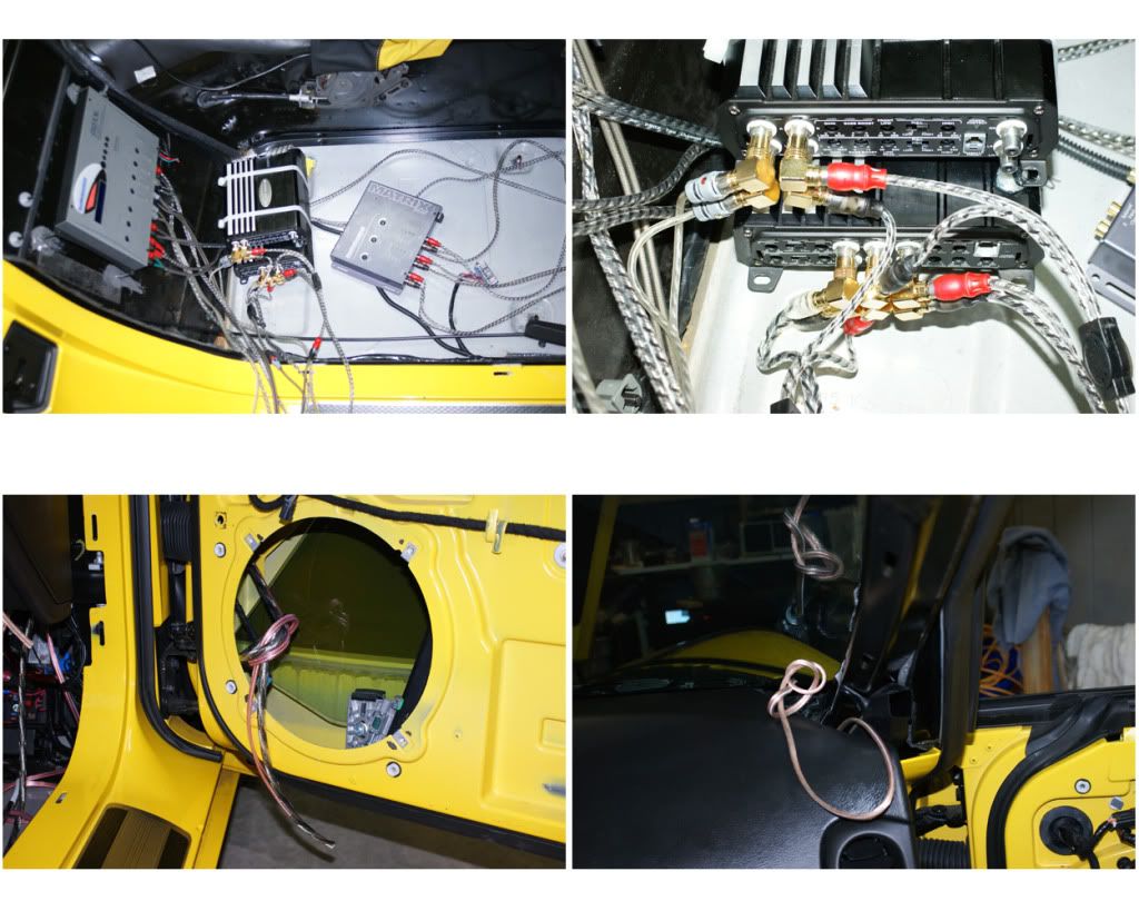
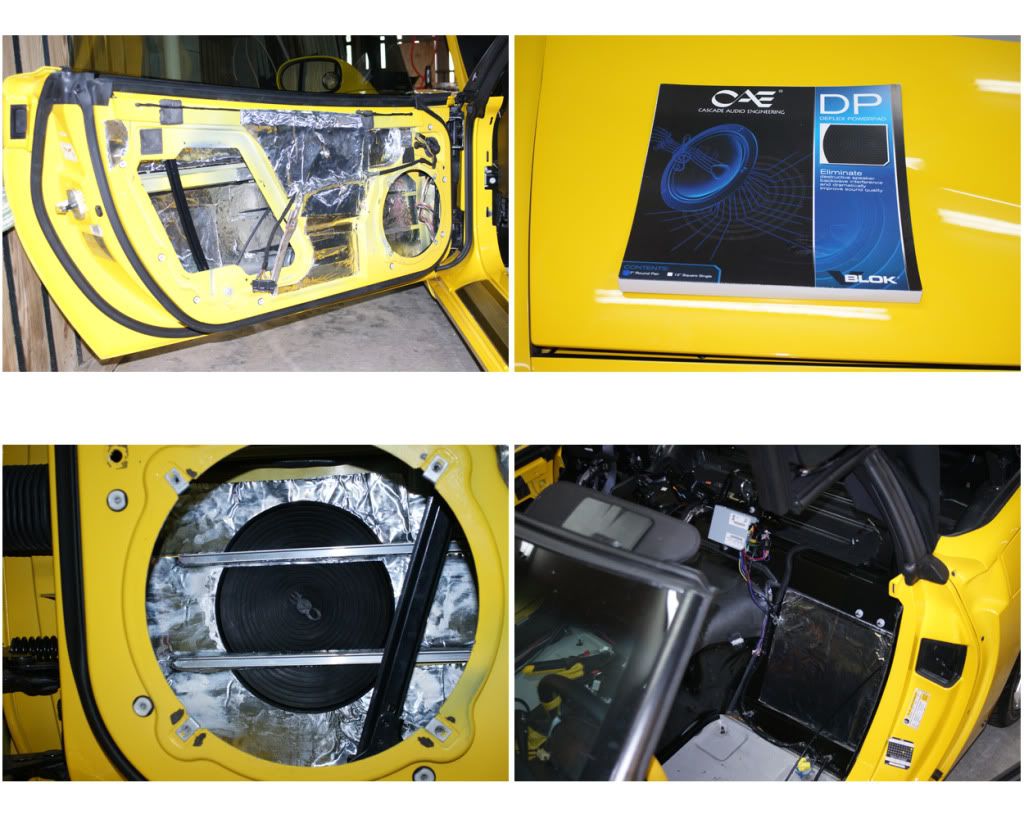
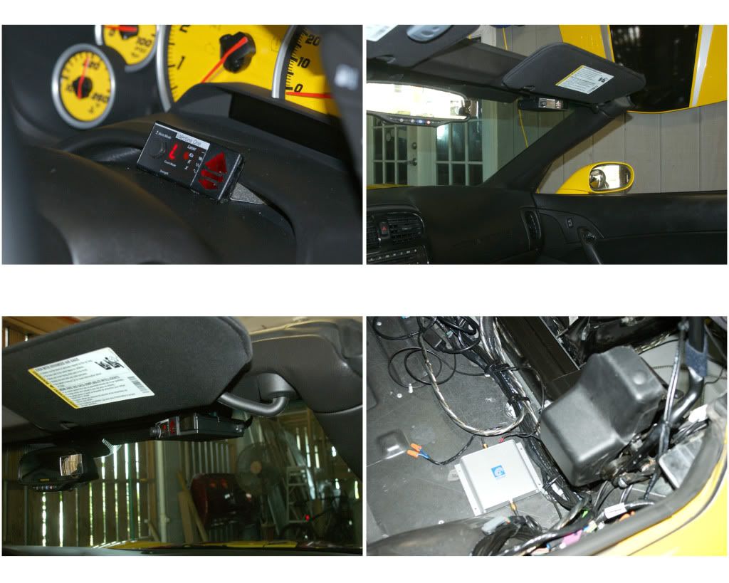
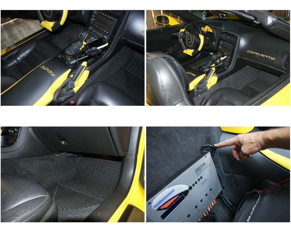
14) AMPLIFIERS: I considered several places to mount my two ARC amps (rear cubbies, behind passenger seat, custom rack in trunk) but decided on the passenger footwell and in such a manner they could be accessed. So I’ll remove the non-Bose amp in the passenger footwell next to the fuse box. First remove the one big blue fuse box connector by lifting the grey lock-bar and pulling outlet up. Next unscrew the four 7mm hex screws at each corner of the amp. Then remove the small gold 5mm hex screws that hold the silver mount-frame on. Then you will have easy access to disconnect the two plugs. The beige plug is a push-spade, the blue plug has a lock-comb to remove on one side and a push-tab on the other, press and pull out. Once removed push plugs up and tuck out of the way. My two amps will be sandwiched together with 7” stainless straps. First I configure the best fit and then test the fit. Due to the heat-sink ribs on the amps, one side would be higher so I added nylon spacers to level. I added small pieces of 3M double-sided tape to each foot and spacer to hold them together for clamping. For my amps to fit I need to remove the left half plastic surround that held the orig. amp, using a Rockwell cutting tool with a fine-toothed metal cutting blade, then cut away the plastic backplate. I fashioned two blocks of wood to hold the amps up and off the floor, sizing and angling it to fit, then added a stop screw & nylon spacer to keep it from sliding back on the block. Once configured I epoxied the blocks in place and used some duct tape to hold it down until cured. After it cured I did another test-fit, then determined a placement for an elevator bolt that will strap the amp down, and epoxied that e-bolt into place, again using duct tape to hold it in place. The strap will screw into the mount hole at the bottom of the fuse box surround. Lastly I add some light foam to the back for cushioning. I’ll mount the amps later after fully connecting all the cables and testing the system.
NOTE: The space was very tight, on KEDAR’s post he used smaller ARC amps, but I had already purchased these thinking they would fit. Turned out they were a bit larger, 6.5“ wide x 11” tall x 4.25“ thick when sandwiched together, and the space was about 7.5” wide and 12“ tall and 5” deep at the max ...


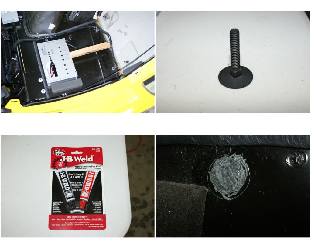
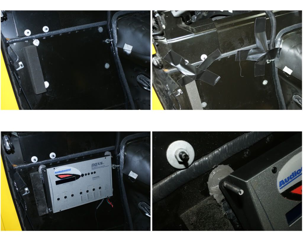
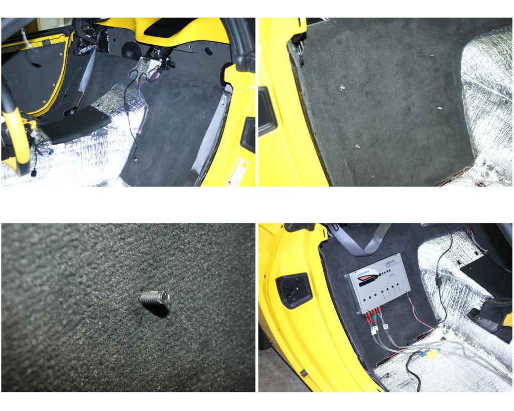
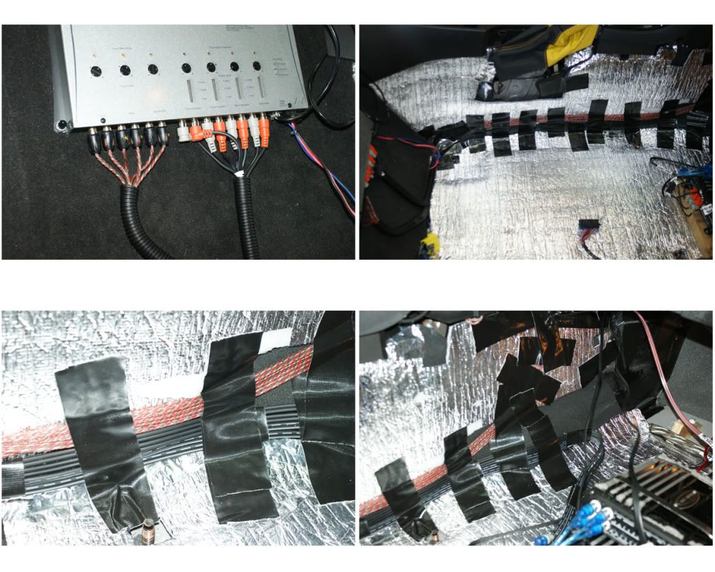
15) AUDIO-CONTROL MATRIX & DQXS: A major upgrade to the system is the 12 volt Matrix line-driver (this ensures a balanced signal and optimal strength) and the DQXS digital processor (this provides a separate 32-band EQ, crossover & level controls for six channels … each pair of the twelve speakers). First we’ll mount the DQXS behind the passenger seat. This unit is nice and slim at 1” thick, so behind the seat works far better than putting the thicker amps there. I played with the placement and settled on the spot. To mount the DQXS I’ll be using 1.5” x .25” elevator-bolts which have a 1” wide head to epoxy in place. I marked the spots for the four bolts, then scuff that area. Mix the epoxy and slather it on the bolt head, then put the two top bolts in place using some Gorilla-tape to keep it there. Once that cured in 12 hours, I confirm the placement then do the lower two bolts. Next is the Matrix placement, this is supposed to be as close to the HU as possible, and found a decent amount of space in the dash between the gauge cluster and HU … test fitting shows it barely fits. I’ll put in some foam padding and get it wedged in once I confirm the control settings. The HU line outs go to it (6“ RCA cables) and then from there to the DQXS (10 feet), and then to the amps (6 feet).
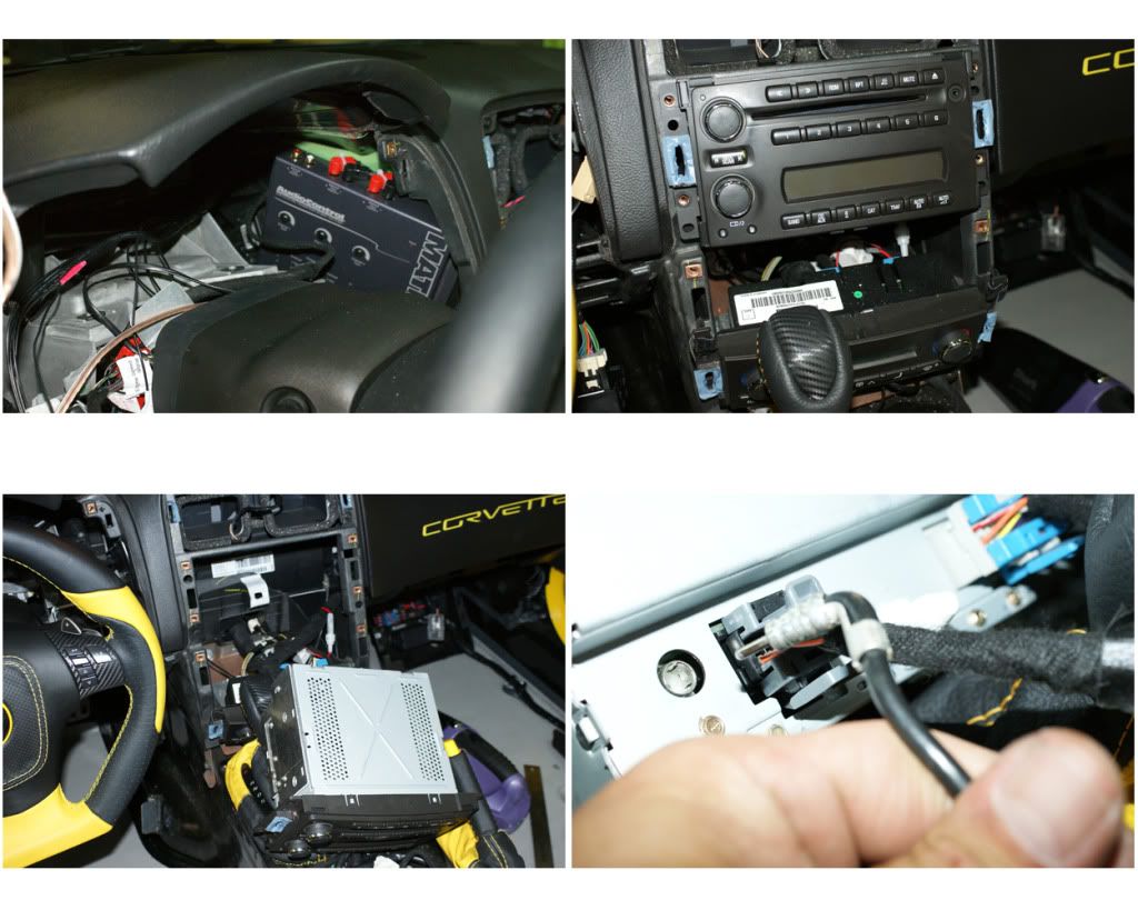
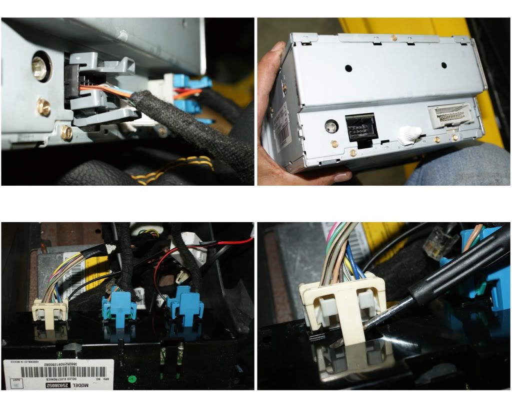
16) HEAD-UNIT: I’ll be using the stock HU for now (maybe upgrade later), but I have to remove it to hook-up everything. First pull-out the HVAC controller by removing the two 7mm screws, then pull out the unit a bit. Now remove the four 7mm HU screws and pull it out. Unplug the antenna and then the two plugs, and set the HU aside. Now remove the HVAC controller (or you could leave in place), it has three plugs (L to R, beige, green and black) and they are easy to unclip. Center console is now clear, time for another refreshing adult beverage …
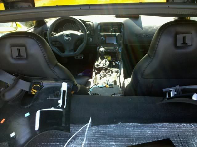
NOTE: At this point all of the interior trim, panels and pieces are removed. Be sure to keep things organized and protected from the elements. I am doing this in my spare time and took me just over a month for the whole install, so I kept the seats, pieces with electrical parts and new pieces inside the house.

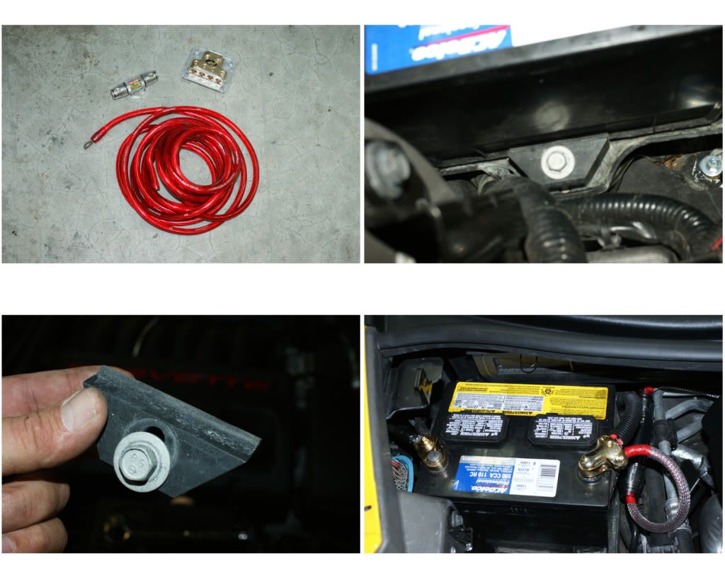
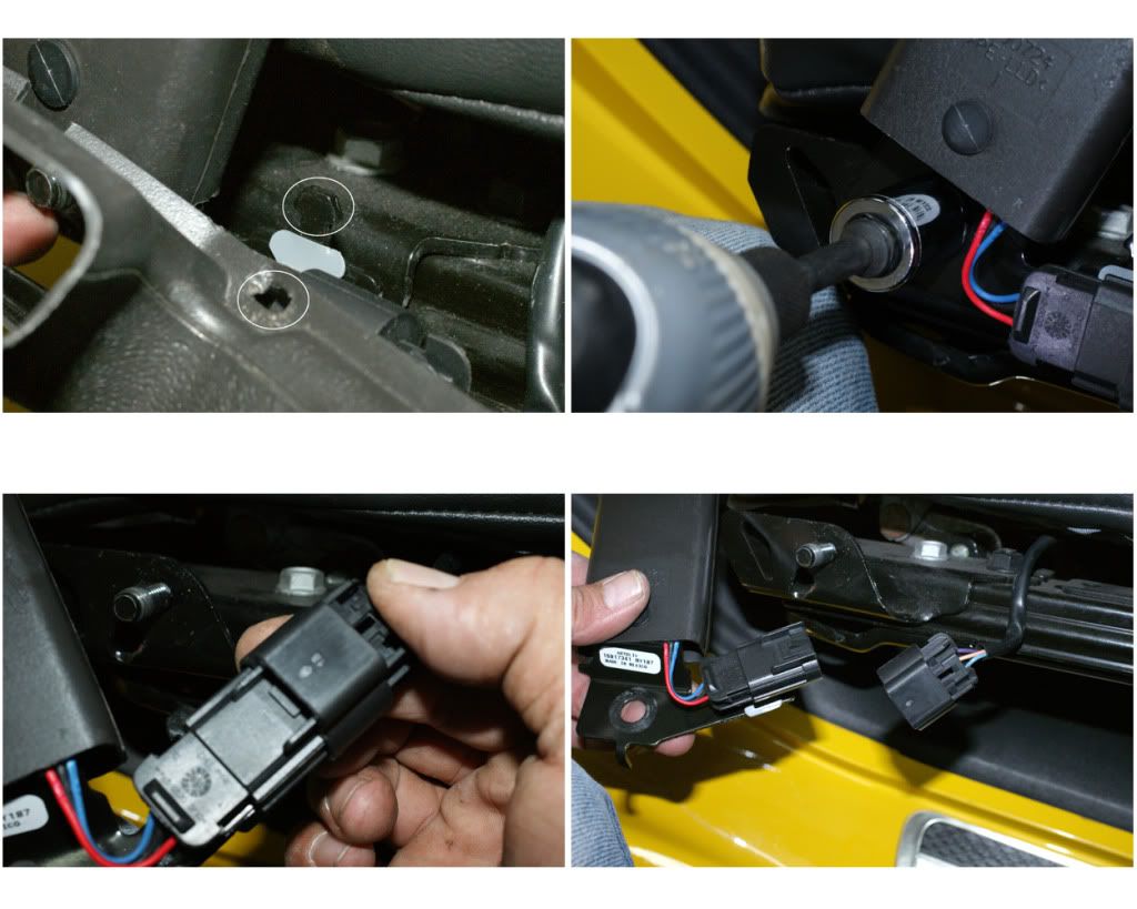
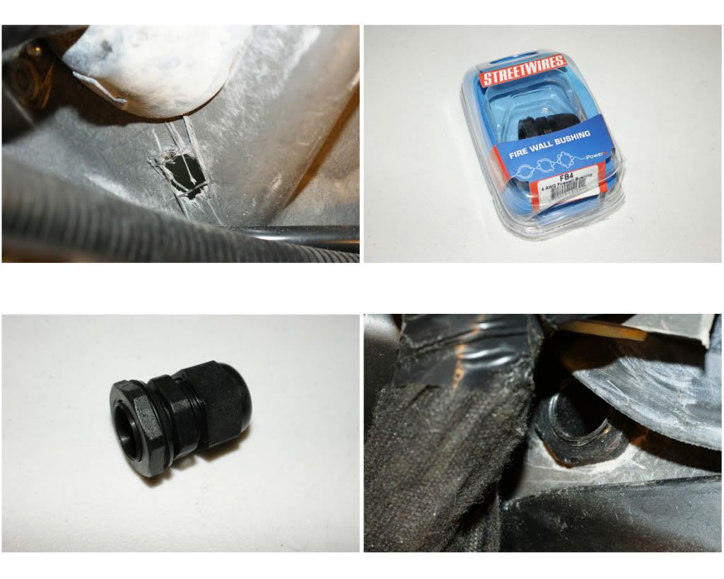
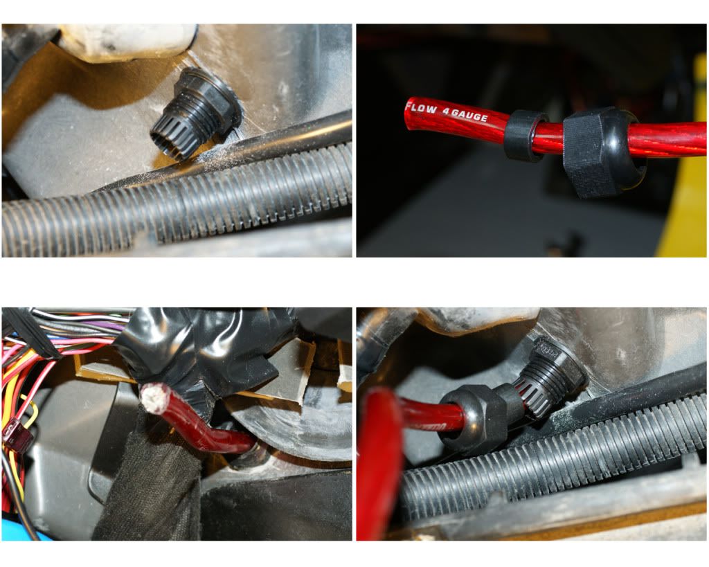
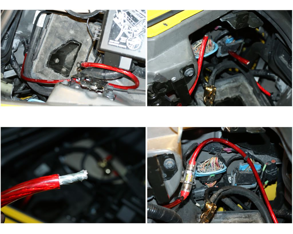
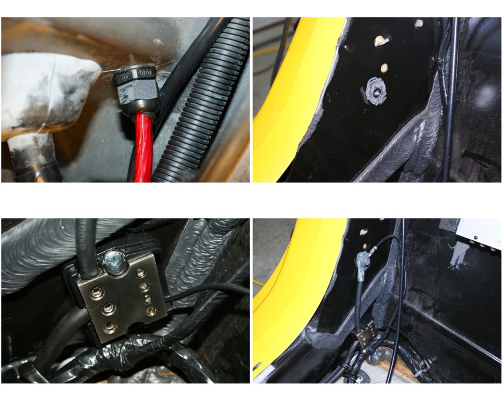
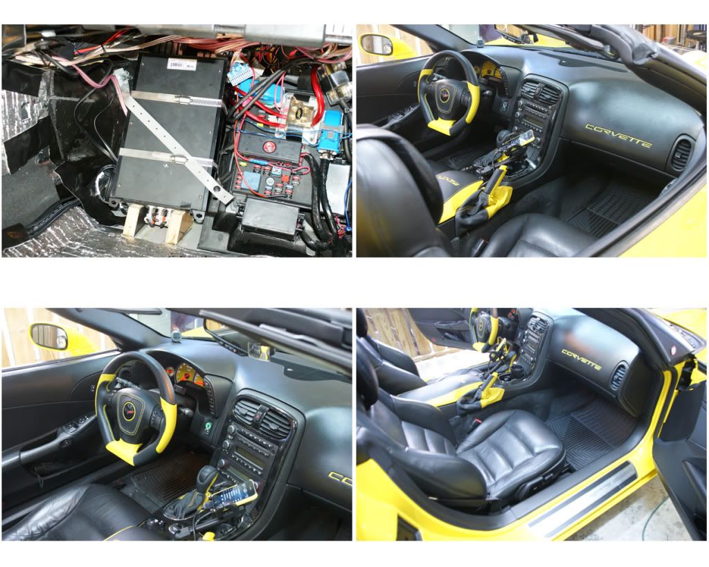
17) NEW POWER CABLES: For my amp and new components I’m running a 4-gauge positive-power wire into the cabin through the firewall. First remove the battery tie-down (13mm bolt at bottom), then your battery post terminals, and pull-out the batt and set aside. The positive cable will connect at the remote power bolt under the engine fuse box, then run to the side and behind the batt, and through the firewall (I’m using a 4-gauge firewall bushing to pass through to a power distribution block. I inspected both the inside footwell and engine side of the firewall and decided on the spot for the bushing, drilling a small pilot hole first, then the .75” hole for the bushing. Installed the bushing from the inside, added the washer and cap to the 10 foot cable and passed it through the bushing into the cabin. Laying out the cable, I picked the spot to add the 125 amp inline fuse, cut the cable and connected the fuse unit, then zip-tied it in place. Now you can tighten the bushing (DO NOT connect the power yet). I now connect the four power wires for the amps, Matrix, DQXS to the dist. block then attach the block to the 4 gauge main cable. The block will be at the top of the fuse panel held in place by a couple of zip ties. For the Remote Power (RAP) circuit I used an Add-A-Circuit in the footwell fuse box plugged into the upper wiper fuse (WPR/WSW) in the far right cube, then crimp legs out to the Matrix, two amps, DQXS and cell-booster. For the negative/ground cable, I’m using the bolt in the passenger door sill. Scuff the area, add some dielectric grease, then the cable, size the wires and mount the dist. block. I ran wires from here to the DQXS and cell-booster, and to a third dist. block in the footwell.

18) SIGNAL & SPEAKER WIRES: I’ll use some old RCA cables I have on hand for now and determine which lengths I need. 6 inches for HU to Matrix, 10 feet for Matrix to DQXS, and 6 feet for DQXS to the amps. For the Matrix and amps to fit in their really tight spaces I will need right-angle plugs, but these separate connector-adapters are too big, so I ordered the molded right-angle twisted patch cables I’ll need. Now on to the speaker wires: I’m using 12-gauge twisted wire from KnuKonceptz for the main speakers and subs, and 14-gauge Monster wire for the 3.5’s and tweets. Starting at the doors, I fished the 2 sets through the rubber door accordions and down through the dash from the pillars, leaving plenty of estimated length into the connection area in the footwell. Ran the rear speakers across the back, down the waterfall and across the floor. The subs ran from the back left cubby to the right cubby (where they will split), then against the right wall, across the back to the waterfall, and along the floor with the rear wires. All wiring has now been laid. Now onto the deadening …
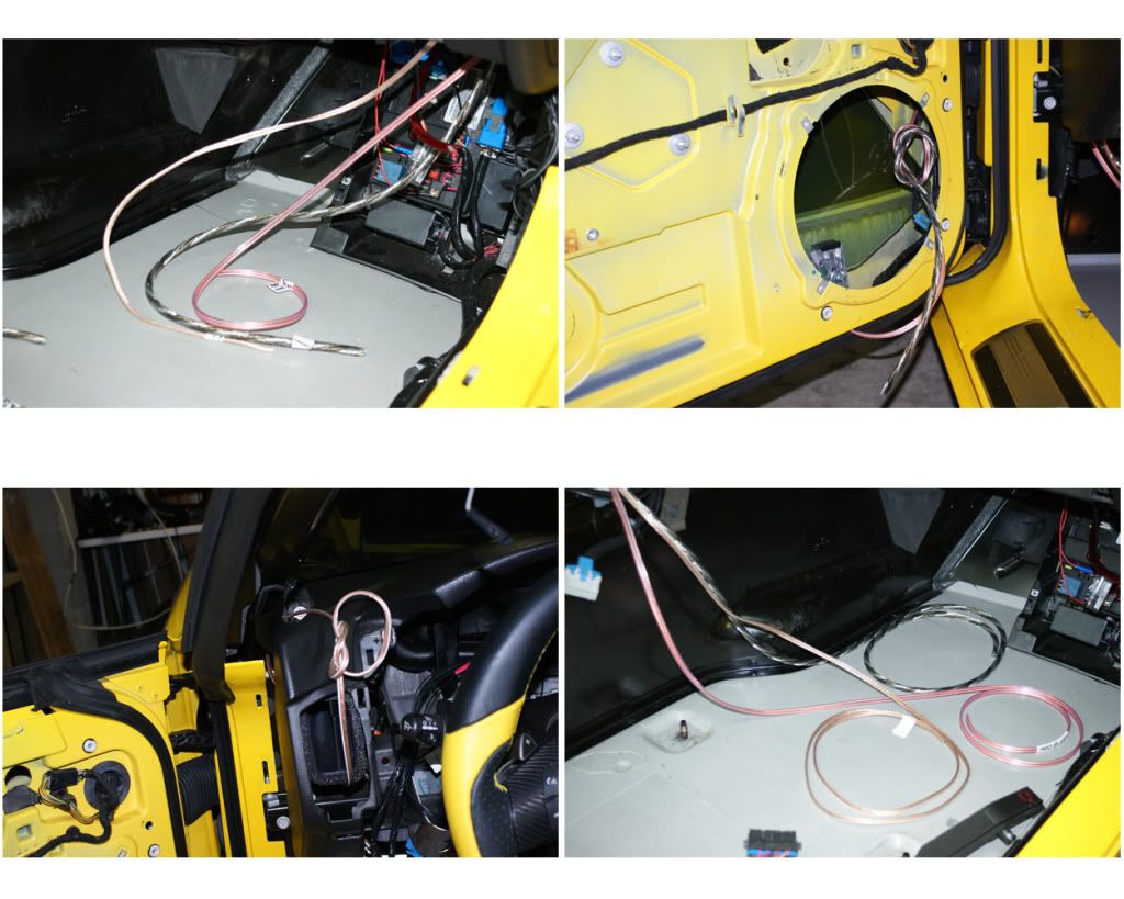
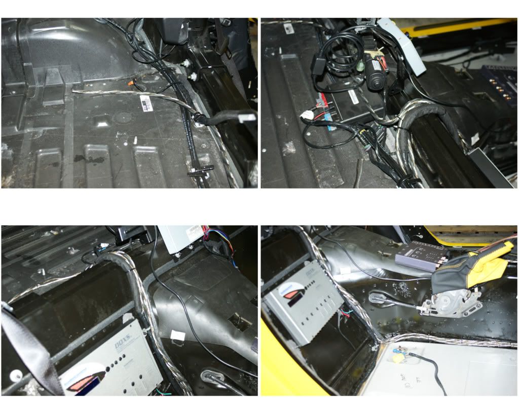
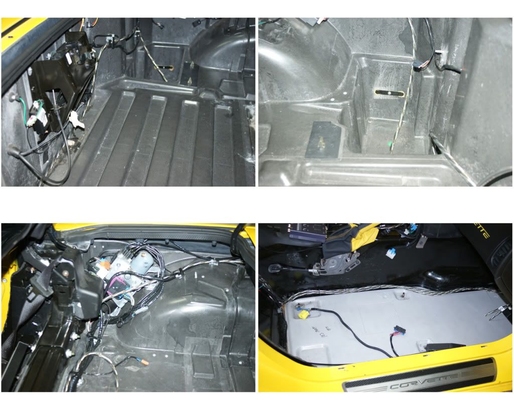
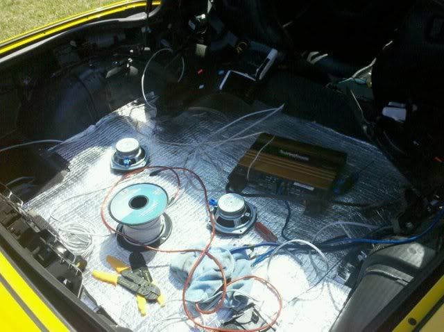
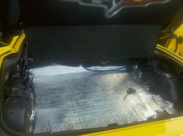
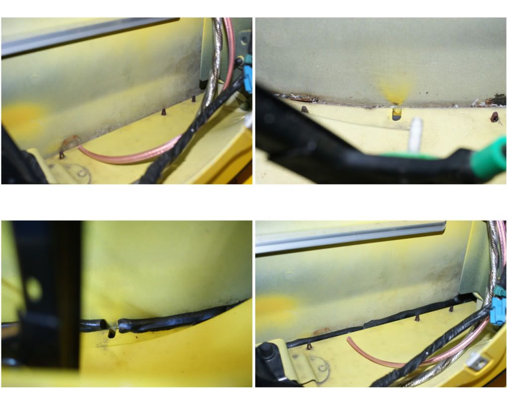
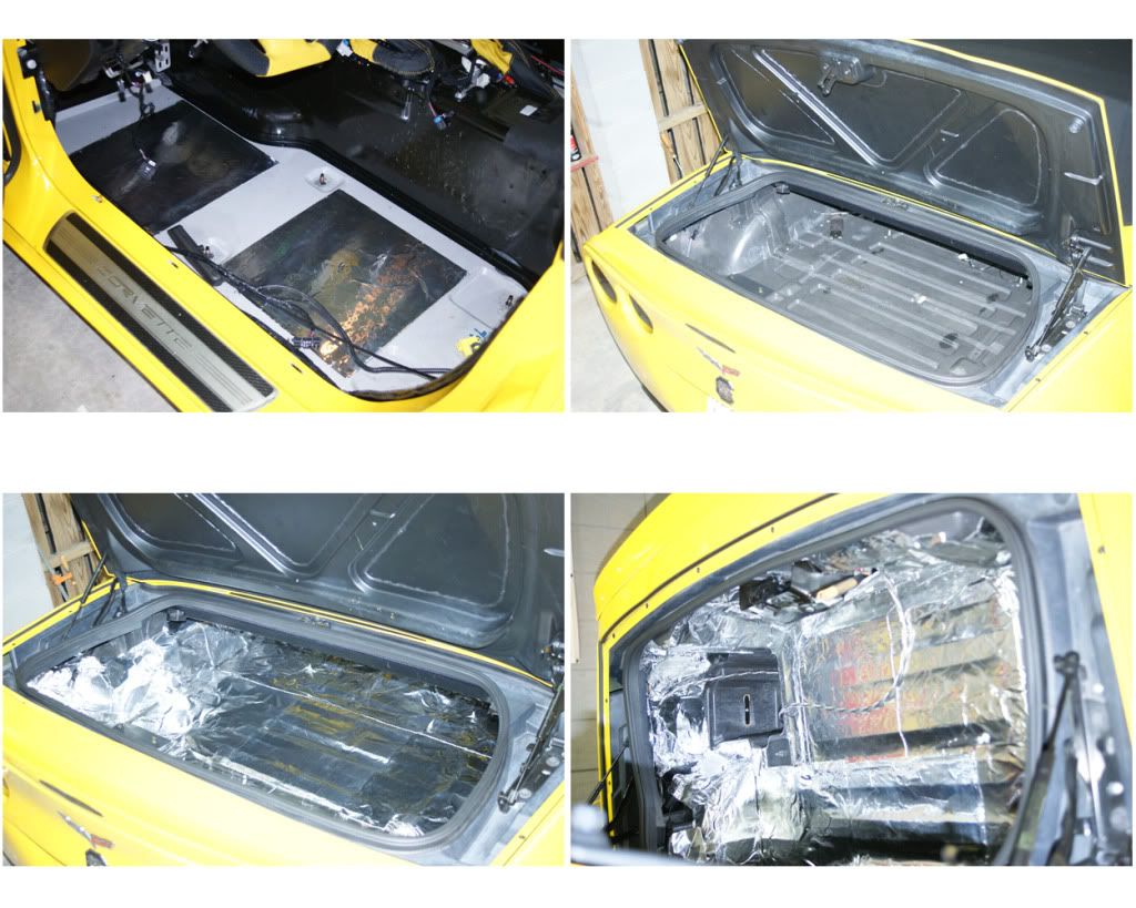
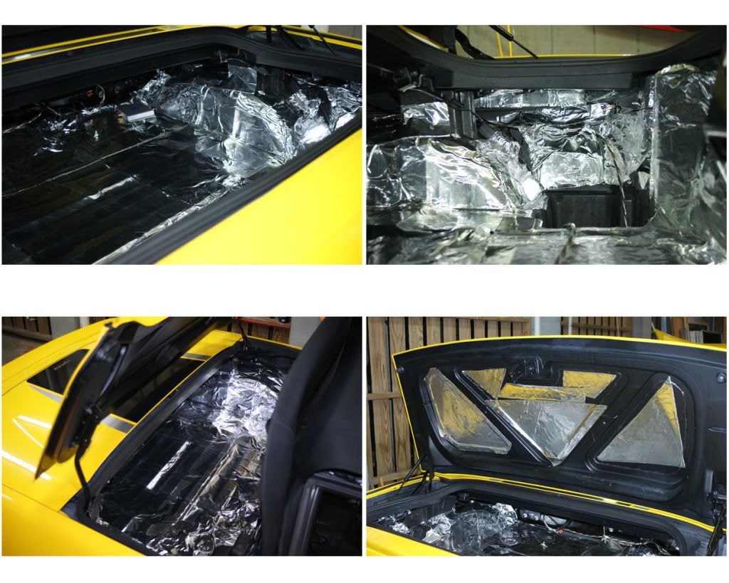
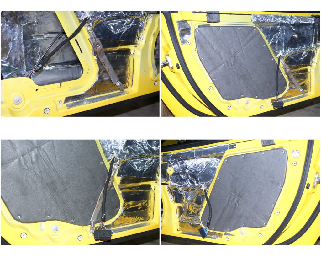
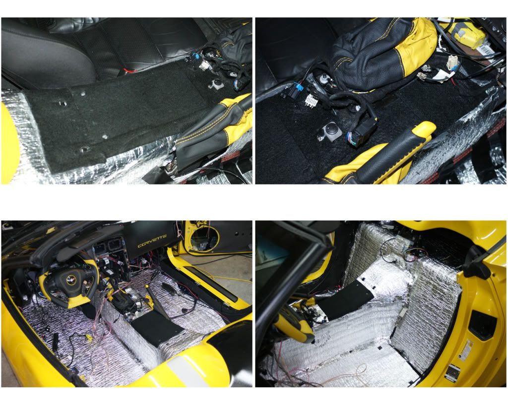
19) DEADENING, LAYER 1 – STIFFENERS, BUTYL & BXTII: Two great suppliers for this first step, 1) RAAM Audio for the BXTII and aluminum door-panel stiffeners, and 2) Sound Deadening Showdown for the extruded butyl rope. To start I wiped down the entire inside and every surface I would be adhering product to, using denatured alcohol and paper towels. Once all surfaces are clean place the aluminum channels on the inside doors, just split the distance and then stick them on securely. Now to the butyl roping, it is an amazing product as it is a semi-solid, can be stretched, is very dense and super-tacky (add hand lotion to your hands frequently for optimal handling results). I will put this in crevices and against opposing panel joints. It is best to work with 6” to one-foot segments at a time, as it stretches nicely and is very sticky. First place it in the upper and lower gaps between the door beam and door skin, leaving spaces for drainage, and getting it in every gap possible to reach. In some of this space you may need to add more butyl to fill the gap. I then ran it along the most upper seam inside the door above the beam. Next I ran it along the very bottom seams inside the door, again leaving spaces for drainage. Now onto the trunk lid. Here there are seams between the panels and I stretch & press it in place to buffer any vibrations from the subs. Same with the tonneau cover, hit all the edges and seams. I then covered it here with electrical tape to keep it from sticking to the top when lowered during the install, but later will cover completely with ensolite. I also used the butyl in a couple of other places, and to seal the 3.5” speakers to their mount rings in the doors. Stick it where ever you think makes sense. Now for the BXTII. These panels are dense rubber with a great peel & stick adhesive side. I put it everywhere inside the door that I could reach, cutting to fit as needed. Once done on the inside I put some on the outside major areas. I now add the CAE Deflex Powerpad, so as to be directly behind the 6.5” door speaker, and just cut them to fit between the door ribs. I then placed the BXTII tiles on the rear wall behind the seats, and two tiles on the floor. Then in the trunk, I covered the floor, side and rear walls completely, but not the cubbies. I then put some pieces on the inside trunk and tonneau lid (ensolite will be covering these later).
NOTE: Here and on the subsequent layers, BE SURE NOT TO COVER WIRE CONNECTORS, i.e. XM module, as well as the two trunk lights, two emergency release cables on the back left side of the trunk and the release handles on the floor at each door.

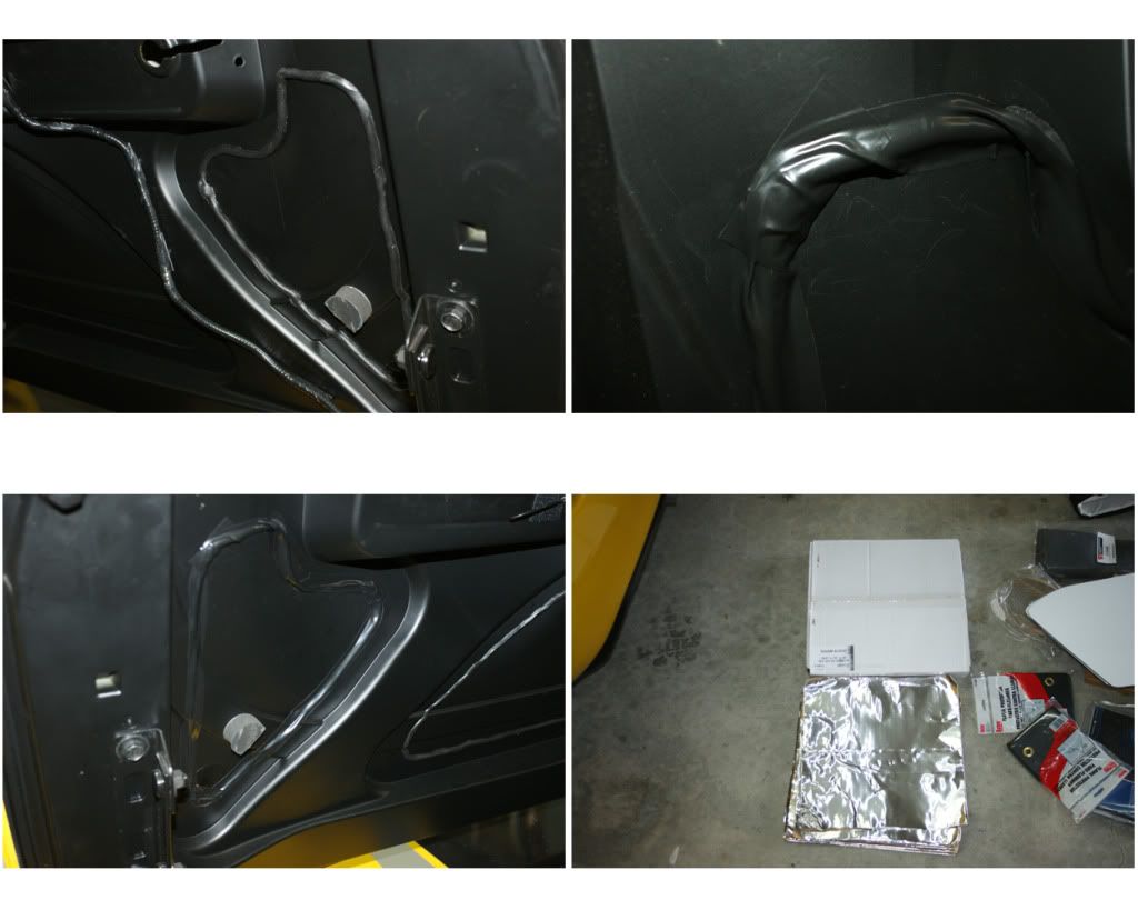
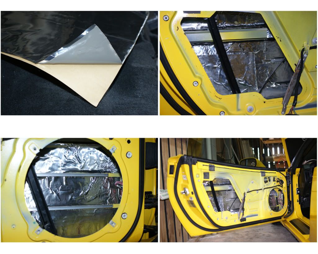
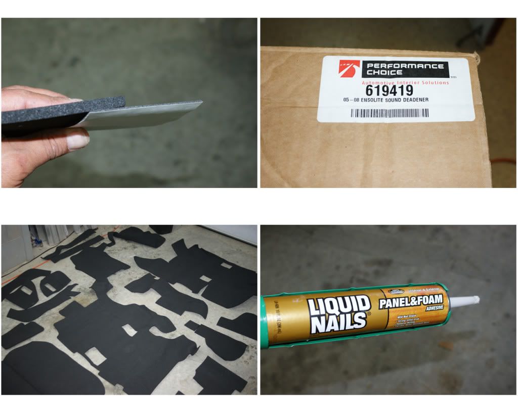
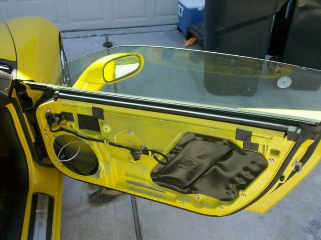
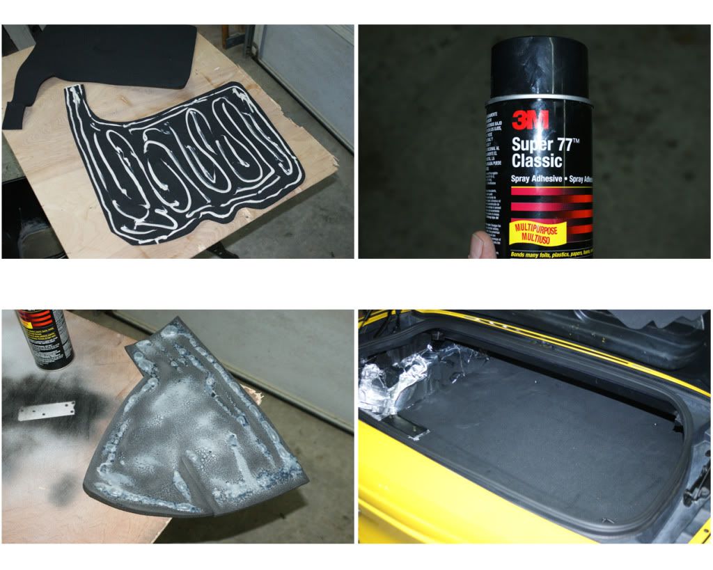
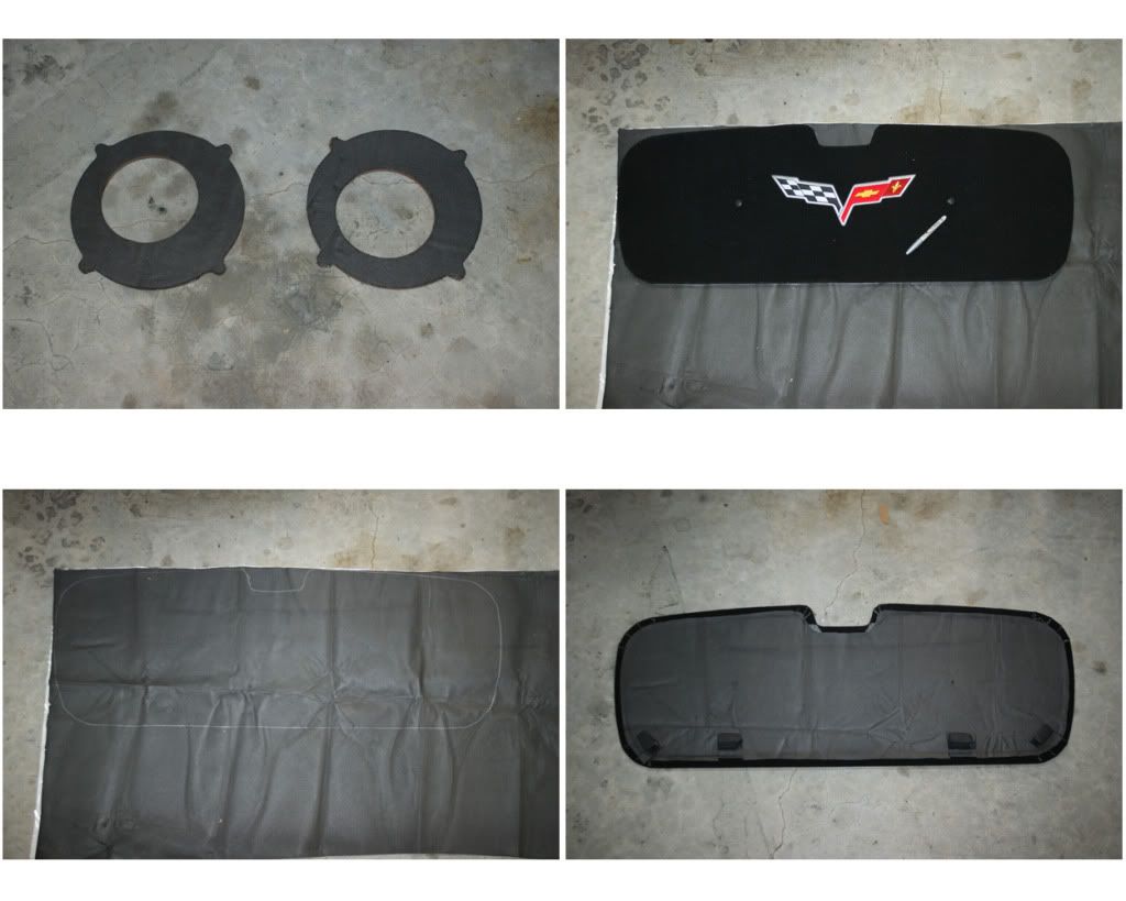
20) DEADENING, LAYER 2 – ENSOLITE: Again, I used two sources for the ensolite. MidAmerica Motorworks (Mamo) and RaamAudio. The Mamo came in two pre-cut kits, one for the entire inside and another for the outer doors. These were .25” thick but were not peel & stick, so I had to use an adhesive. Raam’s came by the yard and were not pre-cut, were only 1/16” thick, but were peel & stick. I think VetteNuts now has a decent pre-cut peel & stick kit. The Mamo kit had several pieces that were not labeled and NO INSTRUCTIONS WERE PROVIDED, so it was difficult to impossible figuring out a few of the pieces. I used Liquid Nails for the larger pieces (it barely works, and takes a month to fully cure) and 3M-77 spray glue for the smaller pieces (this sticks great and I should have just used this on everything). Starting in the trunk test fit each piece (some will require trimming) then put on the adhesive and press in place. Do the same for each piece. I also used Gorilla-tape to help hold pieces here and there. If using the Liquid Nails, go back and press down again every three hours or so. I also ordered the AlumaLite hole covers from Raam, and covered them with the Raam ensolite one side at a time. Move the metal strut on the driver’s door out of the way, loosen the top screw and remove the bottom one then push aside. I then used 10-16 x �” (M4.8 x 19) drill-screws to attach them to the doors, then put the strut back in place. I also covered the speaker plates from NakidParts.com on both sides, as well as the back of the trunk lid cover and underside of the tonneau. The Mamo Door-Quiet ensolite kit came with an optional rope/caulk adhesive, which can be stretched thin. I placed it along the edges and across the inside and put them on. I also put Frost-King duct insulation on the inside of the door panels, this stuff is not very sticky so used Gorilla-tape to secure it better in places, then installed the door speakers. Now only one more layer to go, the heat-shield …

21) DEADENING, LAYER 3 – HEAT-SHIELD: This is a great pre-cut and labeled kit from VetteNuts, that is held in place with their super-silver tape (get 3 or 4 rolls!). Starting in the trunk, put into place then stick down with the tape (it sticks to anything). Do the wheel wells and then work forward. Every piece fit perfectly, but I ran out of silver tape, so used Gorilla-Tape to finish. Next I used two Flame-Protector sheets from Lowe’s to cover the tunnel top from the shifter to the back of the arm rest console. This is nice and thick and will drastically cut down on the heat. Pull out the grommets, then use the spray adhesive. I put the first one down then cut the 2nd one up to fill the rest of the area. That’s it people, deadening done, time to celebrate … with a Beck’s beverage!


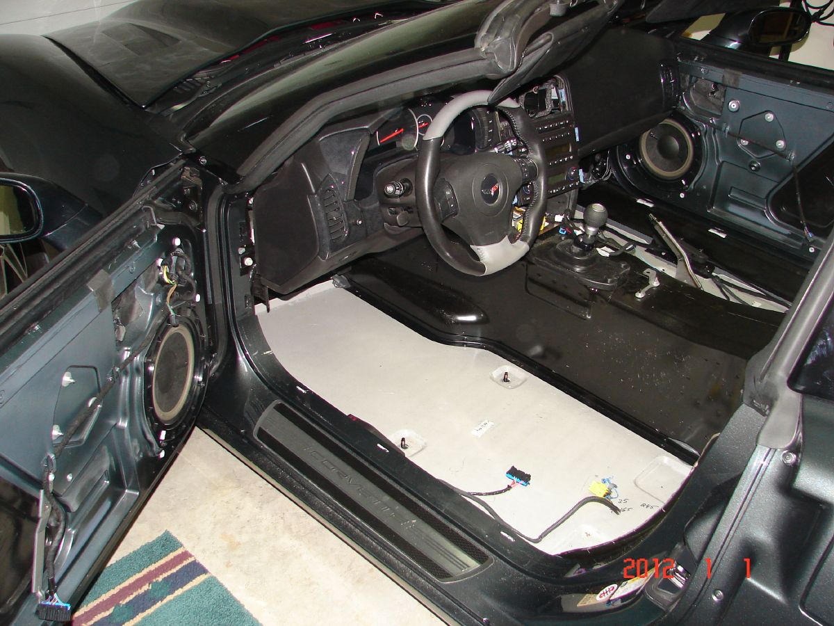
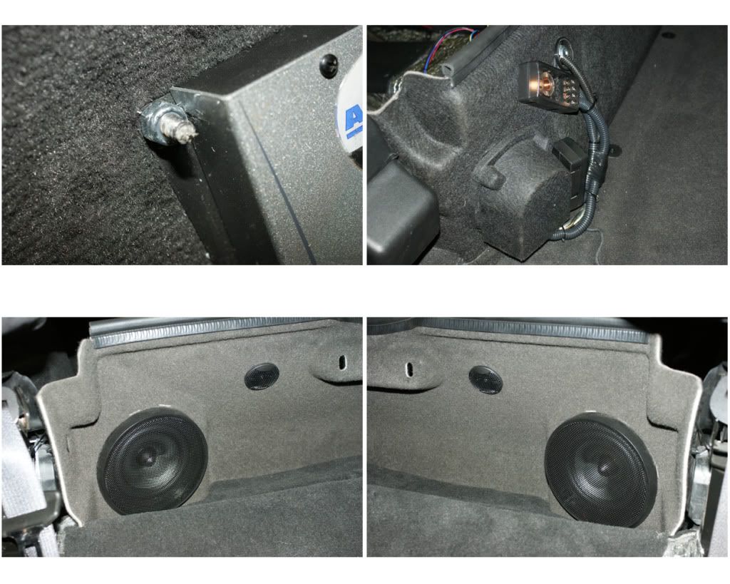
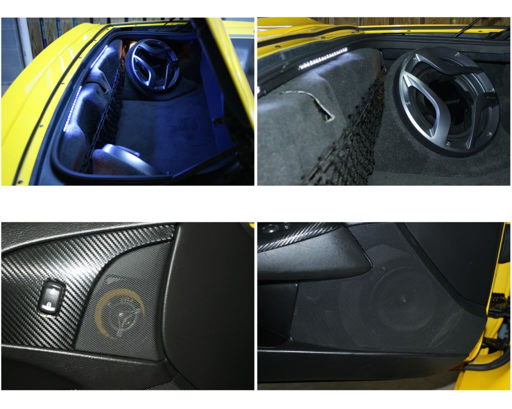
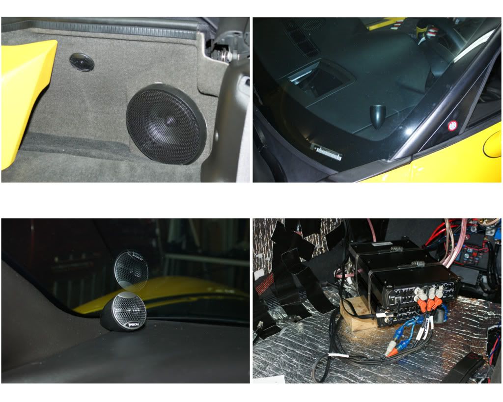
22) CARPET BACK IN & SPEAKERS: Now I reinstall the trunk carpet and the rear walls. WARNING: I had to pull off some stock carpet padding where the partition will sit, at the top of the wheel wells (where the folded top rests) and on the top of the seat wall, otherwise the partition would not fit right and the tonneau would not close down all the way (wish someone had mentioned this in other posts that I read). In the trunk I also had to remove the cubby lid-rings (they were hot-glued to the carpet holes), the deck clips for the rings and some ensolite around the cubbies, or the new sub-pods would not fit due to the overly thick new padding in that area. It was a struggle to get any of the rear fasteners back on through the carpet, so just be aware. So next installed the two subs and pods from VettNuts. Then put the seat wall carpet back in, starting on the driver’s side. There in this incredibly cheap velcro stapled to it that joins it to the rear deck carpet, and had to hot glue it down in most places. On the passenger side I got it into place then cut small slits for the DQXS bolts to poke through. Smoothed everything out nicely, install the DQXS and bolt it down. I had already installed the new component speakers and crossovers on the partition, so just dropped it in and hooked everything up. Next I put the 6.5“ component speakers in the doors. Here you have 4 corner positions on the plate to mount the speaker, and after testing I chose the bottom-front position as that puts it below the dash and in front of your knee. Then I installed the drivers side carpeting (the pass. carpet is all that’s left, but that will be the very last thing to install). The new 3.5” coax go in the doors, installed as the stock ones were using some butyl rope to seal to their cups. Most people put the component tweets here on custom plates, and I may later as well. My plan is to put the front tweets on the pillars and will use velcro to play with their placement before committing to their install, so for now I’ll leave them in their bullet pods and down at the pillar bottom, facing the center of the cabin. That’s all twelve speakers mounted and connected, so ready to connect to the remote power bolt in the engine fuse box. Connected, so I climb in and push the ACC ignition switch … everything powers up, lights are dancing and nothing is on fire.
NOTE: Be sure to get the best RCA cables you can (twisted pairs), and the best speaker wire, like the 12 or 8-gauge twisted KnuKonceptz. When wires are twisted they reduce noise and provide a better signal …
23) SIGNAL WIRES & HEADUNIT: I got the right-angle RCA cables, so now to install the Matrix and connect everything. First is the HU, I had ordered the ADD-GM24 patch connect, to which I soldered female RCA plugs, and GLNI’s as well as an antenna GLNI thingie (but later neither GLNI’s were needed, so took them out). So re-connect the HU plugs and antenna, and with the HU still sitting on the console, connected the cables from the HU to the Matrix (front & rear - L & R, two 6” pairs) - I switched the front and rear channels so the chimes, Bluetooth and OnStar go the the rear left speaker instead of the front left. Next tuck the cables behind the HU and run down back of console and along the side of the tunnel to the DQXS (front, rear and sub – L & R, three 10’ pairs). Then from the DQXS along the floor corner to the amps (front high, front low, rear low and sub – L & R, four 6’ pairs). Now I’ll start testing, make a few final installs, put everything back together and post the final sets of photos. I got the replacement amp today, so have to swap that out and put the passenger carpet in.
NOTE: I hooked-up everything loose before installing to be sure it all worked before bolting it all back in.
13) KILLING CENTER SPEAKER: Two clips are on either side of circular area, pry up on each side, then pry up the two clips on the longer ends, and there’s one last clip in middle rear. Unclip light sensor’s push-spade and remove. Speaker in held by four 7mm screws, remove speaker, disconnect and reinstall -or remove entirely (I left it in place).
14) AMPLIFIERS: I considered several places to mount my two ARC amps (rear cubbies, behind passenger seat, custom rack in trunk) but decided on the passenger footwell and in such a manner they could be accessed. So I’ll remove the non-Bose amp in the passenger footwell next to the fuse box. First remove the one big blue fuse box connector by lifting the grey lock-bar and pulling outlet up. Next unscrew the four 7mm hex screws at each corner of the amp. Then remove the small gold 5mm hex screws that hold the silver mount-frame on. Then you will have easy access to disconnect the two plugs. The beige plug is a push-spade, the blue plug has a lock-comb to remove on one side and a push-tab on the other, press and pull out. Once removed push plugs up and tuck out of the way. My two amps will be sandwiched together with 7” stainless straps. First I configure the best fit and then test the fit. Due to the heat-sink ribs on the amps, one side would be higher so I added nylon spacers to level. I added small pieces of 3M double-sided tape to each foot and spacer to hold them together for clamping. For my amps to fit I need to remove the left half plastic surround that held the orig. amp, using a Rockwell cutting tool with a fine-toothed metal cutting blade, then cut away the plastic backplate. I fashioned two blocks of wood to hold the amps up and off the floor, sizing and angling it to fit, then added a stop screw & nylon spacer to keep it from sliding back on the block. Once configured I epoxied the blocks in place and used some duct tape to hold it down until cured. After it cured I did another test-fit, then determined a placement for an elevator bolt that will strap the amp down, and epoxied that e-bolt into place, again using duct tape to hold it in place. The strap will screw into the mount hole at the bottom of the fuse box surround. Lastly I add some light foam to the back for cushioning. I’ll mount the amps later after fully connecting all the cables and testing the system.
NOTE: The space was very tight, on KEDAR’s post he used smaller ARC amps, but I had already purchased these thinking they would fit. Turned out they were a bit larger, 6.5“ wide x 11” tall x 4.25“ thick when sandwiched together, and the space was about 7.5” wide and 12“ tall and 5” deep at the max ...
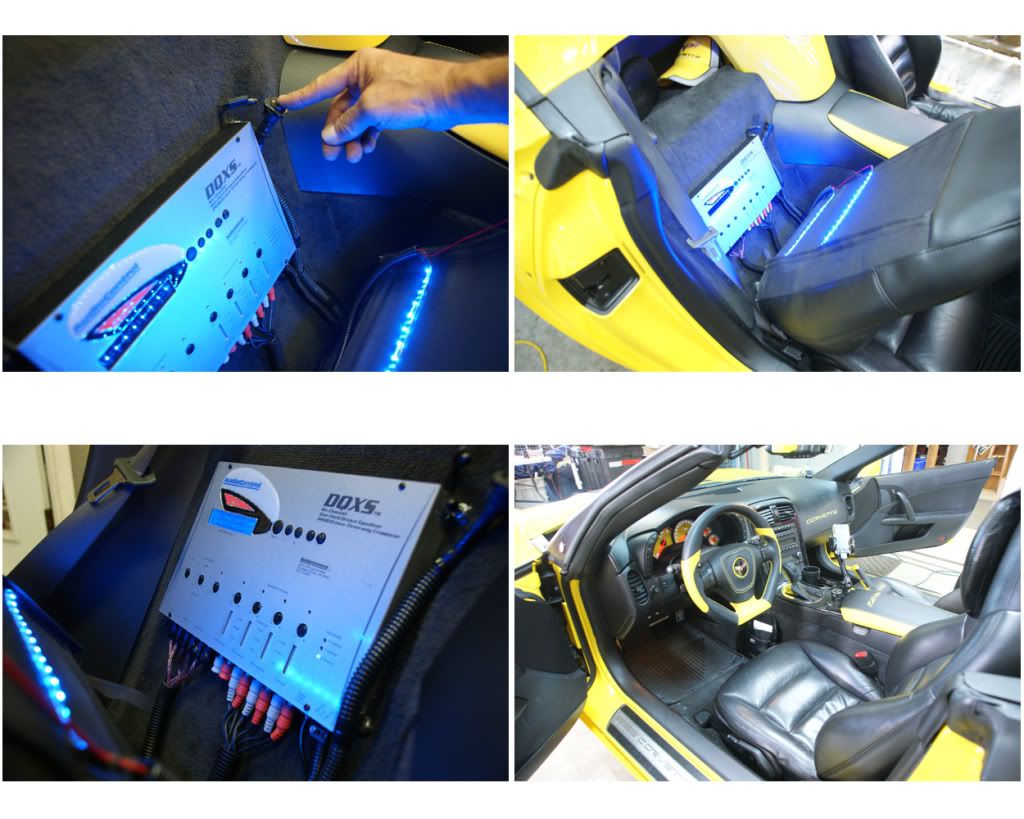
15) AUDIO-CONTROL MATRIX & DQXS: A major upgrade to the system is the 12 volt Matrix line-driver (this ensures a balanced signal and optimal strength) and the DQXS digital processor (this provides a separate 32-band EQ, crossover & level controls for six channels … each pair of the twelve speakers). First we’ll mount the DQXS behind the passenger seat. This unit is nice and slim at 1” thick, so behind the seat works far better than putting the thicker amps there. I played with the placement and settled on the spot. To mount the DQXS I’ll be using 1.5” x .25” elevator-bolts which have a 1” wide head to epoxy in place. I marked the spots for the four bolts, then scuff that area. Mix the epoxy and slather it on the bolt head, then put the two top bolts in place using some Gorilla-tape to keep it there. Once that cured in 12 hours, I confirm the placement then do the lower two bolts. Next is the Matrix placement, this is supposed to be as close to the HU as possible, and found a decent amount of space in the dash between the gauge cluster and HU … test fitting shows it barely fits. I’ll put in some foam padding and get it wedged in once I confirm the control settings. The HU line outs go to it (6“ RCA cables) and then from there to the DQXS (10 feet), and then to the amps (6 feet).
16) HEAD-UNIT: I’ll be using the stock HU for now (maybe upgrade later), but I have to remove it to hook-up everything. First pull-out the HVAC controller by removing the two 7mm screws, then pull out the unit a bit. Now remove the four 7mm HU screws and pull it out. Unplug the antenna and then the two plugs, and set the HU aside. Now remove the HVAC controller (or you could leave in place), it has three plugs (L to R, beige, green and black) and they are easy to unclip. Center console is now clear, time for another refreshing adult beverage …
NOTE: At this point all of the interior trim, panels and pieces are removed. Be sure to keep things organized and protected from the elements. I am doing this in my spare time and took me just over a month for the whole install, so I kept the seats, pieces with electrical parts and new pieces inside the house.
17) NEW POWER CABLES: For my amp and new components I’m running a 4-gauge positive-power wire into the cabin through the firewall. First remove the battery tie-down (13mm bolt at bottom), then your battery post terminals, and pull-out the batt and set aside. The positive cable will connect at the remote power bolt under the engine fuse box, then run to the side and behind the batt, and through the firewall (I’m using a 4-gauge firewall bushing to pass through to a power distribution block. I inspected both the inside footwell and engine side of the firewall and decided on the spot for the bushing, drilling a small pilot hole first, then the .75” hole for the bushing. Installed the bushing from the inside, added the washer and cap to the 10 foot cable and passed it through the bushing into the cabin. Laying out the cable, I picked the spot to add the 125 amp inline fuse, cut the cable and connected the fuse unit, then zip-tied it in place. Now you can tighten the bushing (DO NOT connect the power yet). I now connect the four power wires for the amps, Matrix, DQXS to the dist. block then attach the block to the 4 gauge main cable. The block will be at the top of the fuse panel held in place by a couple of zip ties. For the Remote Power (RAP) circuit I used an Add-A-Circuit in the footwell fuse box plugged into the upper wiper fuse (WPR/WSW) in the far right cube, then crimp legs out to the Matrix, two amps, DQXS and cell-booster. For the negative/ground cable, I’m using the bolt in the passenger door sill. Scuff the area, add some dielectric grease, then the cable, size the wires and mount the dist. block. I ran wires from here to the DQXS and cell-booster, and to a third dist. block in the footwell.
18) SIGNAL & SPEAKER WIRES: I’ll use some old RCA cables I have on hand for now and determine which lengths I need. 6 inches for HU to Matrix, 10 feet for Matrix to DQXS, and 6 feet for DQXS to the amps. For the Matrix and amps to fit in their really tight spaces I will need right-angle plugs, but these separate connector-adapters are too big, so I ordered the molded right-angle twisted patch cables I’ll need. Now on to the speaker wires: I’m using 12-gauge twisted wire from KnuKonceptz for the main speakers and subs, and 14-gauge Monster wire for the 3.5’s and tweets. Starting at the doors, I fished the 2 sets through the rubber door accordions and down through the dash from the pillars, leaving plenty of estimated length into the connection area in the footwell. Ran the rear speakers across the back, down the waterfall and across the floor. The subs ran from the back left cubby to the right cubby (where they will split), then against the right wall, across the back to the waterfall, and along the floor with the rear wires. All wiring has now been laid. Now onto the deadening …
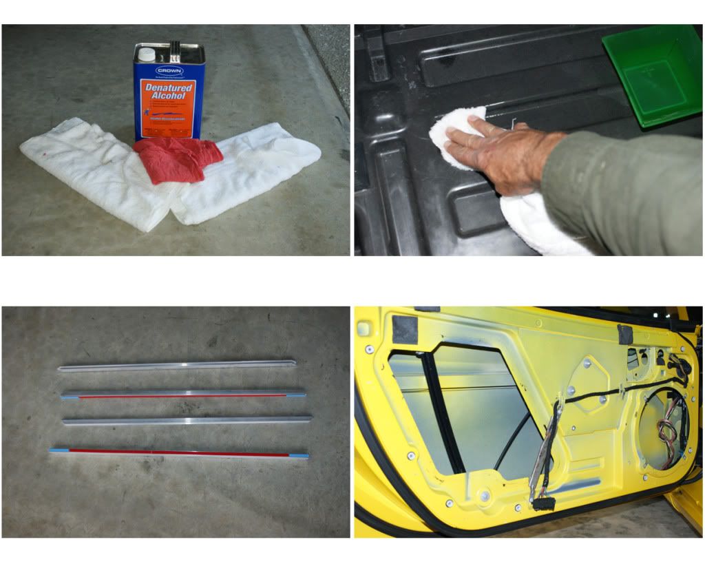
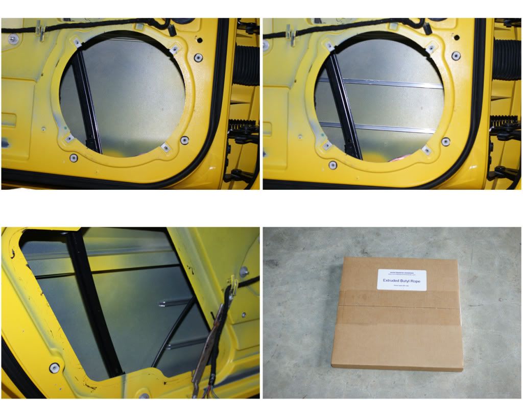
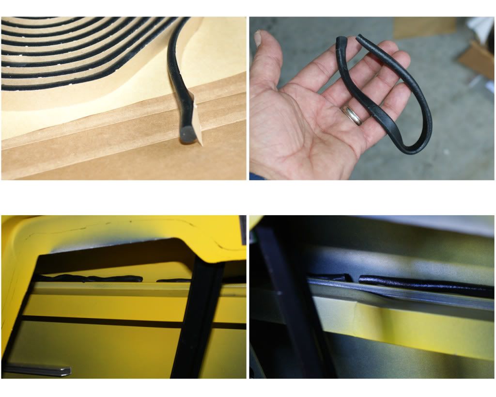
19) DEADENING, LAYER 1 – STIFFENERS, BUTYL & BXTII: Two great suppliers for this first step, 1) RAAM Audio for the BXTII and aluminum door-panel stiffeners, and 2) Sound Deadening Showdown for the extruded butyl rope. To start I wiped down the entire inside and every surface I would be adhering product to, using denatured alcohol and paper towels. Once all surfaces are clean place the aluminum channels on the inside doors, just split the distance and then stick them on securely. Now to the butyl roping, it is an amazing product as it is a semi-solid, can be stretched, is very dense and super-tacky (add hand lotion to your hands frequently for optimal handling results). I will put this in crevices and against opposing panel joints. It is best to work with 6” to one-foot segments at a time, as it stretches nicely and is very sticky. First place it in the upper and lower gaps between the door beam and door skin, leaving spaces for drainage, and getting it in every gap possible to reach. In some of this space you may need to add more butyl to fill the gap. I then ran it along the most upper seam inside the door above the beam. Next I ran it along the very bottom seams inside the door, again leaving spaces for drainage. Now onto the trunk lid. Here there are seams between the panels and I stretch & press it in place to buffer any vibrations from the subs. Same with the tonneau cover, hit all the edges and seams. I then covered it here with electrical tape to keep it from sticking to the top when lowered during the install, but later will cover completely with ensolite. I also used the butyl in a couple of other places, and to seal the 3.5” speakers to their mount rings in the doors. Stick it where ever you think makes sense. Now for the BXTII. These panels are dense rubber with a great peel & stick adhesive side. I put it everywhere inside the door that I could reach, cutting to fit as needed. Once done on the inside I put some on the outside major areas. I now add the CAE Deflex Powerpad, so as to be directly behind the 6.5” door speaker, and just cut them to fit between the door ribs. I then placed the BXTII tiles on the rear wall behind the seats, and two tiles on the floor. Then in the trunk, I covered the floor, side and rear walls completely, but not the cubbies. I then put some pieces on the inside trunk and tonneau lid (ensolite will be covering these later).
NOTE: Here and on the subsequent layers, BE SURE NOT TO COVER WIRE CONNECTORS, i.e. XM module, as well as the two trunk lights, two emergency release cables on the back left side of the trunk and the release handles on the floor at each door.
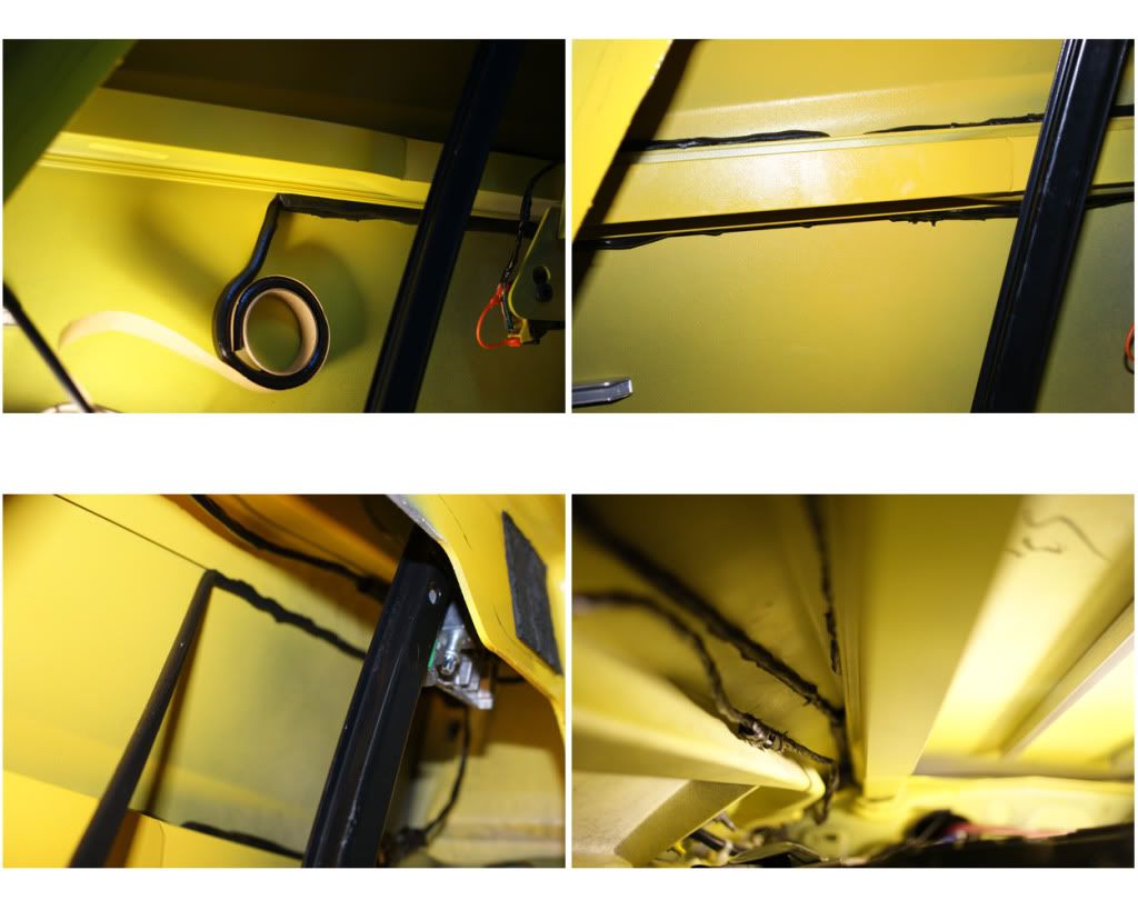
20) DEADENING, LAYER 2 – ENSOLITE: Again, I used two sources for the ensolite. MidAmerica Motorworks (Mamo) and RaamAudio. The Mamo came in two pre-cut kits, one for the entire inside and another for the outer doors. These were .25” thick but were not peel & stick, so I had to use an adhesive. Raam’s came by the yard and were not pre-cut, were only 1/16” thick, but were peel & stick. I think VetteNuts now has a decent pre-cut peel & stick kit. The Mamo kit had several pieces that were not labeled and NO INSTRUCTIONS WERE PROVIDED, so it was difficult to impossible figuring out a few of the pieces. I used Liquid Nails for the larger pieces (it barely works, and takes a month to fully cure) and 3M-77 spray glue for the smaller pieces (this sticks great and I should have just used this on everything). Starting in the trunk test fit each piece (some will require trimming) then put on the adhesive and press in place. Do the same for each piece. I also used Gorilla-tape to help hold pieces here and there. If using the Liquid Nails, go back and press down again every three hours or so. I also ordered the AlumaLite hole covers from Raam, and covered them with the Raam ensolite one side at a time. Move the metal strut on the driver’s door out of the way, loosen the top screw and remove the bottom one then push aside. I then used 10-16 x �” (M4.8 x 19) drill-screws to attach them to the doors, then put the strut back in place. I also covered the speaker plates from NakidParts.com on both sides, as well as the back of the trunk lid cover and underside of the tonneau. The Mamo Door-Quiet ensolite kit came with an optional rope/caulk adhesive, which can be stretched thin. I placed it along the edges and across the inside and put them on. I also put Frost-King duct insulation on the inside of the door panels, this stuff is not very sticky so used Gorilla-tape to secure it better in places, then installed the door speakers. Now only one more layer to go, the heat-shield …
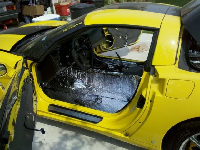
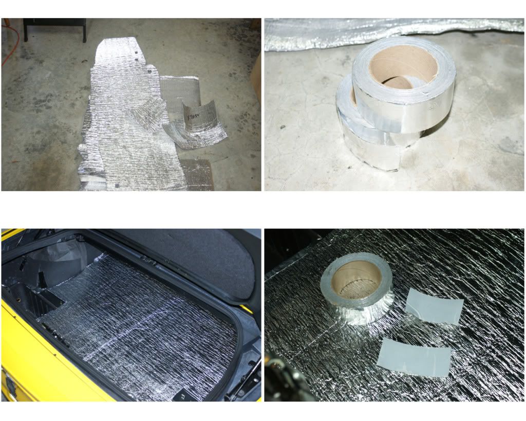
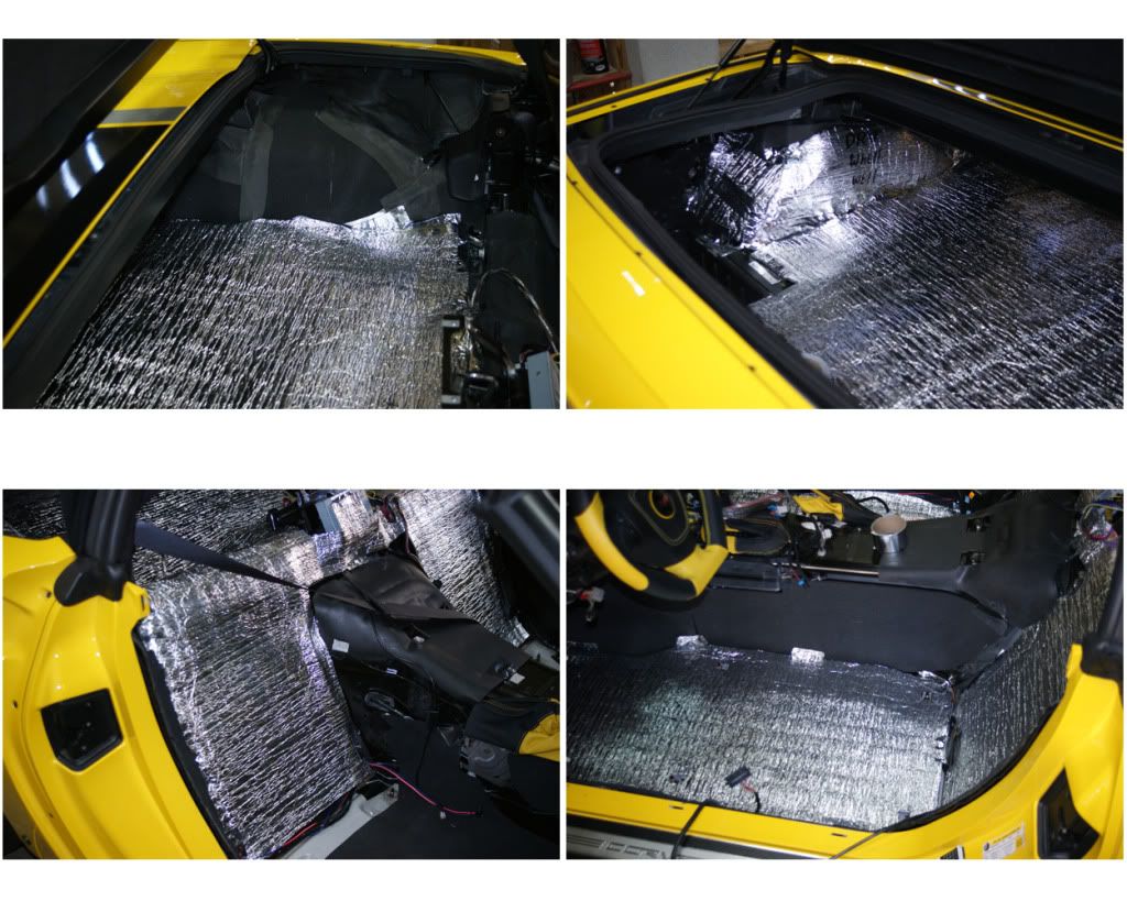
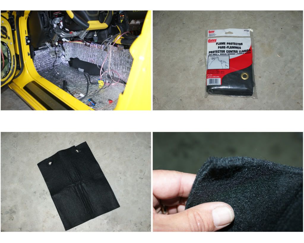
21) DEADENING, LAYER 3 – HEAT-SHIELD: This is a great pre-cut and labeled kit from VetteNuts, that is held in place with their super-silver tape (get 3 or 4 rolls!). Starting in the trunk, put into place then stick down with the tape (it sticks to anything). Do the wheel wells and then work forward. Every piece fit perfectly, but I ran out of silver tape, so used Gorilla-Tape to finish. Next I used two Flame-Protector sheets from Lowe’s to cover the tunnel top from the shifter to the back of the arm rest console. This is nice and thick and will drastically cut down on the heat. Pull out the grommets, then use the spray adhesive. I put the first one down then cut the 2nd one up to fill the rest of the area. That’s it people, deadening done, time to celebrate … with a Beck’s beverage!
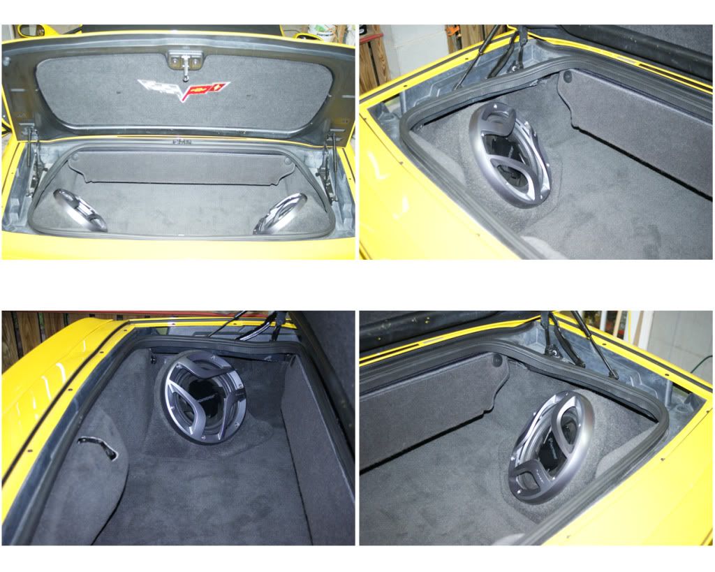
22) CARPET BACK IN & SPEAKERS: Now I reinstall the trunk carpet and the rear walls. WARNING: I had to pull off some stock carpet padding where the partition will sit, at the top of the wheel wells (where the folded top rests) and on the top of the seat wall, otherwise the partition would not fit right and the tonneau would not close down all the way (wish someone had mentioned this in other posts that I read). In the trunk I also had to remove the cubby lid-rings (they were hot-glued to the carpet holes), the deck clips for the rings and some ensolite around the cubbies, or the new sub-pods would not fit due to the overly thick new padding in that area. It was a struggle to get any of the rear fasteners back on through the carpet, so just be aware. So next installed the two subs and pods from VettNuts. Then put the seat wall carpet back in, starting on the driver’s side. There in this incredibly cheap velcro stapled to it that joins it to the rear deck carpet, and had to hot glue it down in most places. On the passenger side I got it into place then cut small slits for the DQXS bolts to poke through. Smoothed everything out nicely, install the DQXS and bolt it down. I had already installed the new component speakers and crossovers on the partition, so just dropped it in and hooked everything up. Next I put the 6.5“ component speakers in the doors. Here you have 4 corner positions on the plate to mount the speaker, and after testing I chose the bottom-front position as that puts it below the dash and in front of your knee. Then I installed the drivers side carpeting (the pass. carpet is all that’s left, but that will be the very last thing to install). The new 3.5” coax go in the doors, installed as the stock ones were using some butyl rope to seal to their cups. Most people put the component tweets here on custom plates, and I may later as well. My plan is to put the front tweets on the pillars and will use velcro to play with their placement before committing to their install, so for now I’ll leave them in their bullet pods and down at the pillar bottom, facing the center of the cabin. That’s all twelve speakers mounted and connected, so ready to connect to the remote power bolt in the engine fuse box. Connected, so I climb in and push the ACC ignition switch … everything powers up, lights are dancing and nothing is on fire.
NOTE: Be sure to get the best RCA cables you can (twisted pairs), and the best speaker wire, like the 12 or 8-gauge twisted KnuKonceptz. When wires are twisted they reduce noise and provide a better signal …
23) SIGNAL WIRES & HEADUNIT: I got the right-angle RCA cables, so now to install the Matrix and connect everything. First is the HU, I had ordered the ADD-GM24 patch connect, to which I soldered female RCA plugs, and GLNI’s as well as an antenna GLNI thingie (but later neither GLNI’s were needed, so took them out). So re-connect the HU plugs and antenna, and with the HU still sitting on the console, connected the cables from the HU to the Matrix (front & rear - L & R, two 6” pairs) - I switched the front and rear channels so the chimes, Bluetooth and OnStar go the the rear left speaker instead of the front left. Next tuck the cables behind the HU and run down back of console and along the side of the tunnel to the DQXS (front, rear and sub – L & R, three 10’ pairs). Then from the DQXS along the floor corner to the amps (front high, front low, rear low and sub – L & R, four 6’ pairs). Now I’ll start testing, make a few final installs, put everything back together and post the final sets of photos. I got the replacement amp today, so have to swap that out and put the passenger carpet in.
NOTE: I hooked-up everything loose before installing to be sure it all worked before bolting it all back in.
Last edited by Thrash; 02-19-2013 at 09:47 AM.
01-31-2012, 11:36 PM
#10
Former Vendor

awesome Bill, my wife is actually pissed with me for insullation on mine. She can't keep her feet warm now lol.

 02-01-2012, 09:21 PM
#13
Drifting
And how many Becks had to sacrifice their lives!
02-02-2012, 05:41 PM
#14
Melting Slicks
Thread Starter
Well it was not really very much trouble to do the photos, and it proved worthwhile on the re-install. Many Becks were sacrificed indeed. Now for the conclusion to the install ...
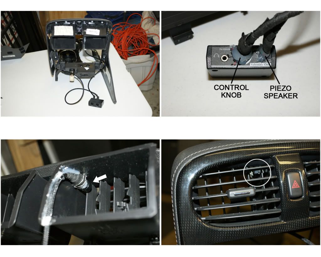
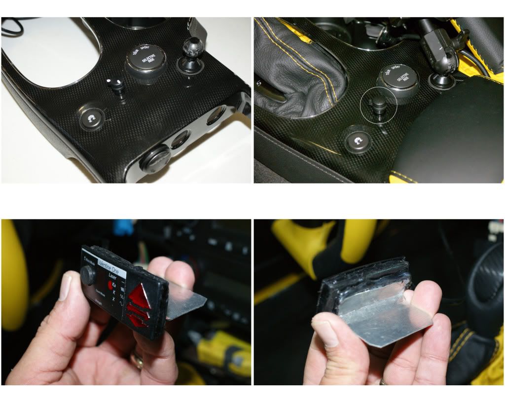
24) VALENTINE ONE & Z-BOOST: I also hacked my Valentine-One radar detector: 1) Cut and resoldered the Concealed Display (CD) down to �” thick and mounted it on top of the steering column. 2) Ordered a custom RemoteAudioAdaptor (RAA) from Radar-Mirror <CLICK HERE> where the control **** is wired-out as a remote, mounting that to the center console next to the mag-ride ****, and they also wired-out the mini-speaker (you have to ask them to do this part), and mounted that inside the top-left-center air duct, pointing at my head-ears, this way I control the whole detector from the one remote switch. 3) Mounted the V1 main unit to a concealed area next to the OnStar brick, where it is somewhat behind the tint, turn the volumes all the way down on this and the sound will only come from the RAA’s duct-speaker ... the power module is behind the HU - stealthy! I also installed the Wi-Ex Z-Boost YX230 Car-Extender, that boosts your cell-phone antenna by up to 6-times, mounting the base unit under the carpet on the rear deck behind the passenger seat (below the vert-top controls), then ran the receiver pad from there to the top inside of the center dash. The antenna was run down the right side to the back, through the rear wall and mounted on the inside top of the rear bumper. Powered by clipping into the 12v RAP and ground block. It works amazingly well.
25) BACK TOGETHER: Now that the audio testing and adjusting is done, I re-installed all the modules, trim, carpet, panels and seat, though I had installed the driver’s side items earlier. During the whole install, I kept the car as disassembled as possible so I could go in and make changes & adjustments as needed, which happened several times. I also had the battery on a trickle-charger until I got the new one. Again, there were some thickness problems with the three deadening layers, the door sills were a bit puffy as were the rear wheel wells, partition area and tunnel. Using fewer layers may be a consideration and a coupe would have fewer build-up issues.
26) FINAL TOUCHES: Now everything is sounding super, I have pillar tweets, 3.5” coax in the upper doors, 6.5” mids on lower doors, 5.25” mids and tweeter components in the rear, and two BOOMING 10” sub-pods in the trunk corners. All of these are adjustable (in pairs) by the DQXS, to include levels, active crossover selection, 32-band EQ, all saved to selectable presets, selectable and changed with the DQXS’s wired or wireless remote control, hardly seems fair, eh? I then spent the better part of a day adjusting all of the amp controls to logical and appropriate settings. I also hacked the two ARC amp level-remotes and made a custom mount in the ashtray area, a **** for the pillar tweets and one for the subs. I organized all the signal & speaker wires with zip-ties so that I can pull out the amp when needed to make adjustments. I tested and tested, loud and mild for an hour or more several times. I also put in LED light-strips (from Advance Auto Parts) and a switch on the back of the pass. seat so as to see and adjust the DQXS when needed. And since the sub-pods were blocking the trunk corner lights, I put LED strips in the back along the inside edge of the rear trunk weather seal, wired to the stock lights so they come on when the trunk opens, and they light up the trunk cavity nicely. I also put in a new AutoCraft Gold battery (since mine was almost 3 years old) and new KnuKonceptz battery terminals, as they just looked too cool to pass on.
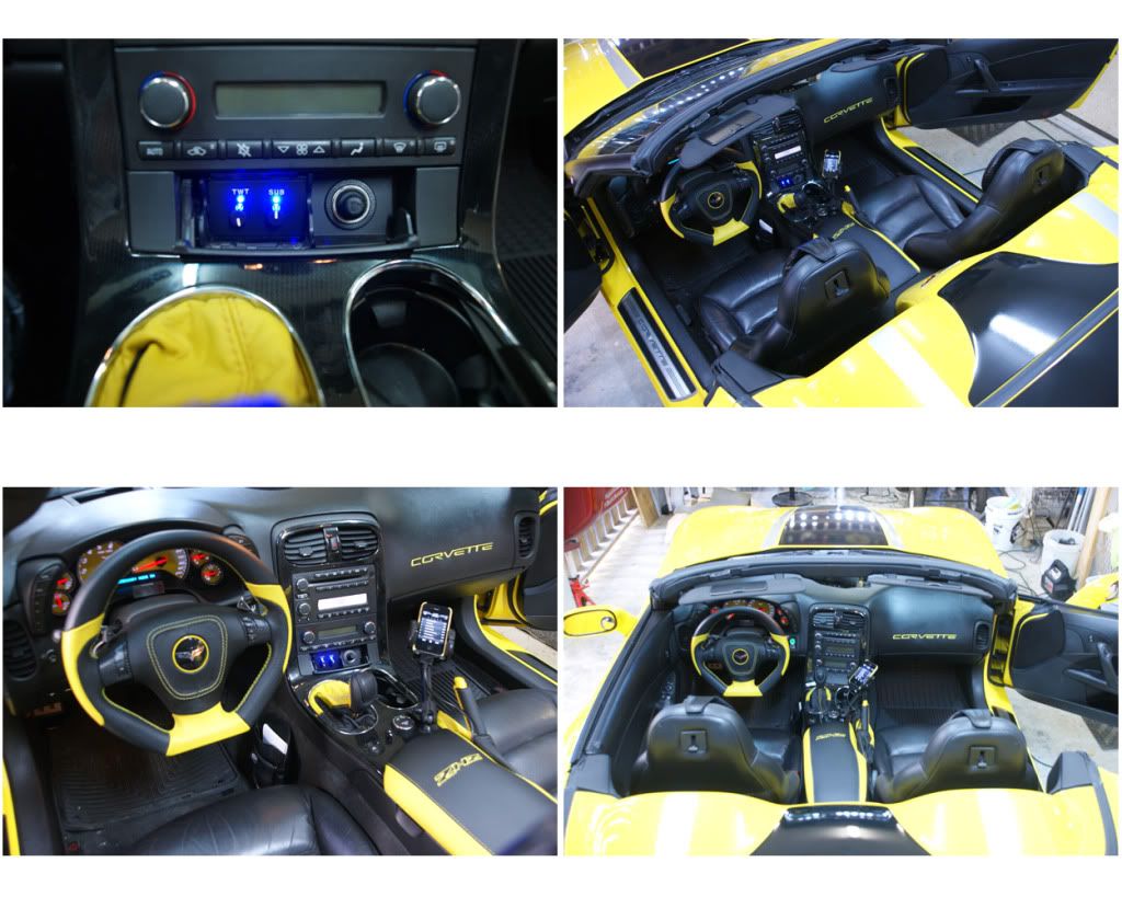

SO ALL DONE ... It sounds amazing. The sound deadening makes a huge difference and the stereo sound is incredible, crisp highs, solid mids and thundering bass. All of these photos can be accessed on PhotoBucket <CLICK HERE> <http://s1103.photobucket.com/home/wrthrash/index> and browse the albums. PM me if you have questions or need advice, or stop by if you are in the Charleston SC area. It was well worth the $5K to have maybe the best Vette-audio ever.
24) VALENTINE ONE & Z-BOOST: I also hacked my Valentine-One radar detector: 1) Cut and resoldered the Concealed Display (CD) down to �” thick and mounted it on top of the steering column. 2) Ordered a custom RemoteAudioAdaptor (RAA) from Radar-Mirror <CLICK HERE> where the control **** is wired-out as a remote, mounting that to the center console next to the mag-ride ****, and they also wired-out the mini-speaker (you have to ask them to do this part), and mounted that inside the top-left-center air duct, pointing at my head-ears, this way I control the whole detector from the one remote switch. 3) Mounted the V1 main unit to a concealed area next to the OnStar brick, where it is somewhat behind the tint, turn the volumes all the way down on this and the sound will only come from the RAA’s duct-speaker ... the power module is behind the HU - stealthy! I also installed the Wi-Ex Z-Boost YX230 Car-Extender, that boosts your cell-phone antenna by up to 6-times, mounting the base unit under the carpet on the rear deck behind the passenger seat (below the vert-top controls), then ran the receiver pad from there to the top inside of the center dash. The antenna was run down the right side to the back, through the rear wall and mounted on the inside top of the rear bumper. Powered by clipping into the 12v RAP and ground block. It works amazingly well.
25) BACK TOGETHER: Now that the audio testing and adjusting is done, I re-installed all the modules, trim, carpet, panels and seat, though I had installed the driver’s side items earlier. During the whole install, I kept the car as disassembled as possible so I could go in and make changes & adjustments as needed, which happened several times. I also had the battery on a trickle-charger until I got the new one. Again, there were some thickness problems with the three deadening layers, the door sills were a bit puffy as were the rear wheel wells, partition area and tunnel. Using fewer layers may be a consideration and a coupe would have fewer build-up issues.
26) FINAL TOUCHES: Now everything is sounding super, I have pillar tweets, 3.5” coax in the upper doors, 6.5” mids on lower doors, 5.25” mids and tweeter components in the rear, and two BOOMING 10” sub-pods in the trunk corners. All of these are adjustable (in pairs) by the DQXS, to include levels, active crossover selection, 32-band EQ, all saved to selectable presets, selectable and changed with the DQXS’s wired or wireless remote control, hardly seems fair, eh? I then spent the better part of a day adjusting all of the amp controls to logical and appropriate settings. I also hacked the two ARC amp level-remotes and made a custom mount in the ashtray area, a **** for the pillar tweets and one for the subs. I organized all the signal & speaker wires with zip-ties so that I can pull out the amp when needed to make adjustments. I tested and tested, loud and mild for an hour or more several times. I also put in LED light-strips (from Advance Auto Parts) and a switch on the back of the pass. seat so as to see and adjust the DQXS when needed. And since the sub-pods were blocking the trunk corner lights, I put LED strips in the back along the inside edge of the rear trunk weather seal, wired to the stock lights so they come on when the trunk opens, and they light up the trunk cavity nicely. I also put in a new AutoCraft Gold battery (since mine was almost 3 years old) and new KnuKonceptz battery terminals, as they just looked too cool to pass on.
SO ALL DONE ... It sounds amazing. The sound deadening makes a huge difference and the stereo sound is incredible, crisp highs, solid mids and thundering bass. All of these photos can be accessed on PhotoBucket <CLICK HERE> <http://s1103.photobucket.com/home/wrthrash/index> and browse the albums. PM me if you have questions or need advice, or stop by if you are in the Charleston SC area. It was well worth the $5K to have maybe the best Vette-audio ever.
Last edited by Thrash; 02-06-2012 at 10:59 PM.
02-02-2012, 07:22 PM
#16
Supporting Vendor
Member Since: Sep 2007
Location: Pensacola Florida GO GATORS!!! www.rlsebring.com www.c6c7vette.com
Posts: 11,216
Received 174 Likes
on
92 Posts
St. Jude Donor '17

Thrash This should be made into an audio manual. Definately saving this thread. I won't be as elaborate with the deadning or audio but now I see how to get it done.
Andy, I'll probably stop by and just happen to bring all my deadning materials with me...
Andy, I'll probably stop by and just happen to bring all my deadning materials with me...
 02-02-2012, 08:04 PM
#17
Former Vendor
02-02-2012, 10:25 PM
#18
Melting Slicks
Thread Starter
[QUOTE=RLSebring;1579904876]Thrash This should be made into an audio manual. Definately saving this thread. I won't be as elaborate with the deadning or audio but now I see how to get it done.
I understand you did my headlight painting via EC Performance, thanks and love the new look. Also, don't be lazy with deadening, do the full 3-layers and you won't be sorry.
I understand you did my headlight painting via EC Performance, thanks and love the new look. Also, don't be lazy with deadening, do the full 3-layers and you won't be sorry.
Last edited by Thrash; 02-02-2012 at 10:28 PM.
02-02-2012, 10:45 PM
#19
Supporting Vendor
Member Since: Sep 2007
Location: Pensacola Florida GO GATORS!!! www.rlsebring.com www.c6c7vette.com
Posts: 11,216
Received 174 Likes
on
92 Posts
St. Jude Donor '17
Those turned out sharp. The black trim rings make a hell of a difference. I think this mod to the trim rings is going places. I have a set of Velocity Yellow rings ready to install against the black bezels. I'll post of pics in the for sale and general sections when finished.
[quote=Thrash;1579906652]
[quote=Thrash;1579906652]
Thrash This should be made into an audio manual. Definately saving this thread. I won't be as elaborate with the deadning or audio but now I see how to get it done.
I understand you did my headlight painting via EC Performance, thanks and love the new look. Also, don't be lazy with deadening, do the full 3-layers and you won't be sorry.
I understand you did my headlight painting via EC Performance, thanks and love the new look. Also, don't be lazy with deadening, do the full 3-layers and you won't be sorry.
02-02-2012, 11:55 PM
#20
Team Owner


Awesome install man! I'm in the middle of mine. I have everything out and am just waiting on some pieces from RaamAudio. Damn that reminds me, I ran out of the BXT II. Too bad you don't live closer I'd try and bribe you for help with some beers

