
How-To repair EBCM avoiding costly repairs through ABSfixer or Fleabay
 04-14-2011, 09:59 AM
#1
Drifting

Thread Starter

For 2001 and later C5's
This is my first write up for CorvetteForum and without this Forum I would not have been able to repair my own EBCM. Bear with me as I may have forgotten something or may not have been too clear in my explanation.
Please feel free to ask any questions.
First, if you don�t already know how, you�ll want to Pull Your Codes
Next, I will direct you to the Electrical Info Thread where you should try to take care of any issues you could have in the ground points. (Thanks to Bill Curlee for the thread)
Once the grounds have been cleaned and taken care of we�ll move on to the removal of the EBCM. I'm aware that step 7 says to send it to ABSfixer. Disregard that step and we'll proceed to the disassembly of the EBCM.
Items required:
Soldering Iron
Solder
De-Solder braid or pump
1 Phillips Screw Driver
Exacto Knife
Tube of Silicone Sealent
Now in order to remove the case I followed these steps:
1. remove 4 x screws
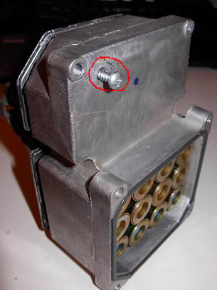
2. remove silicon from that hole on the back lower corner of the EBCM.
3. use a 2BA (or similar) 'thread tap' to cut a thread in that hole
4. screw matching thread screw/bolt into hole, (it misses pcb inside) until it touches cover plate (screw/bolt needs to be 3" long max).
5. carry on winding the screw in until it starts pushing the cover plate away enough to break that gasket seal and allow space to insert those flat blade screwdrivers and work around the remainder. (Thank You JerseyC5)
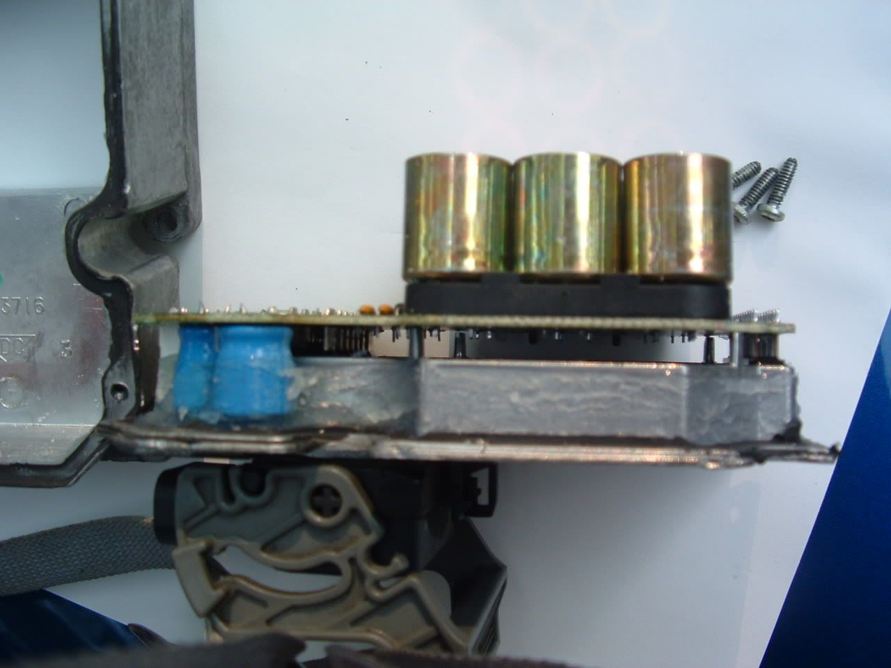
But if you�re like me you won�t have a tap to make a nice threaded hole. I was lucky and found a screw long enough and small enough to be threaded by hand. This is used to apply enough pressure so the back would separate. Refer to the image and said screw I used:
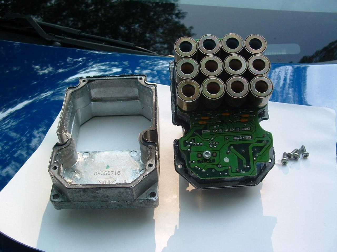
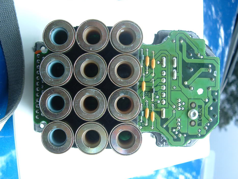
Once the EBCM is taken apart it will look this (Once again Thank You Bill Curlee):
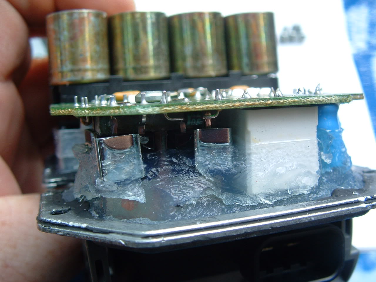
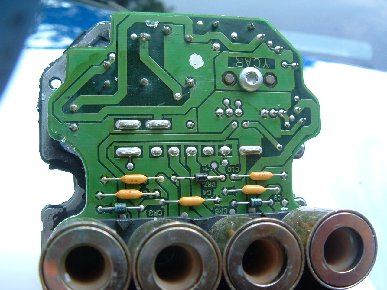
You may need some good lighting and possibly a magnifying glass to inspect the solder points of 5posts.
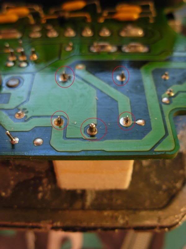
This most likely, as with so many others on the Forum causing the C1214 code. You need to get a soldering iron and some solder to re-solder any point that looks questionable. Once done you will want to test the EBCM, so put the box back together WITHOUT sealant and temp install the EBCM in your C5. Clear any codes before starting your car and you should be ok to start her up and check for any DIC messages.
If you have no messages then you've successfully repaired your own EBCM. Remove the EBCM apply some silicone and put the box back together completely. Install the EBCM using the steps here in reverse.
For replacing relay
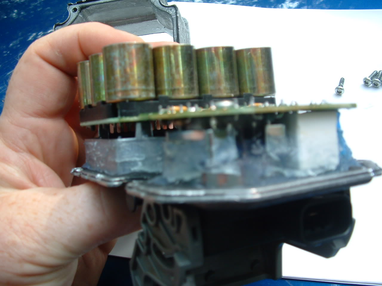
If you suspect or may want to buy a new relay as a �just in case,� you�ll need to Go HEREand place an order for a new relay (The relay PB1321-ND HAS BEEN SUPERCEDED BY N000ORWH-SH-112D, N000 & the link is current with this info). You�ll also need to remove the silicone that�s surrounding the relay like so
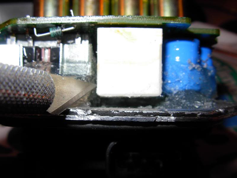
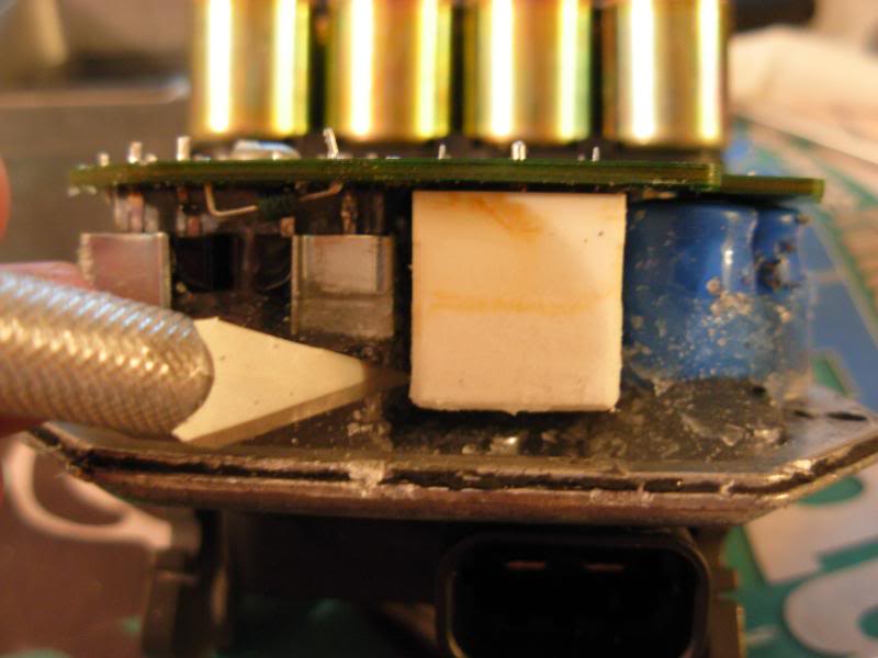
Be very careful to not cut anything around the relay or the Circuit Board. Once the silicone is removed de-solder the points and cut a small amount off of each post in order to lower the relay and slide it out.
Take the new relay and just like the relay you removed, you may have to cut some material off each post to get it to fit. Install the relay, solder the points and refer to the instructions for install above.
Hopefully this makes enough sense for you guys to follow. Again if you have any questions feel free to ask.
Thanks to everyone who helped me and to the members who had previous info on this stupid C1214 code.
nvusgt
This is my first write up for CorvetteForum and without this Forum I would not have been able to repair my own EBCM. Bear with me as I may have forgotten something or may not have been too clear in my explanation.
Please feel free to ask any questions.
First, if you don�t already know how, you�ll want to Pull Your Codes
Next, I will direct you to the Electrical Info Thread where you should try to take care of any issues you could have in the ground points. (Thanks to Bill Curlee for the thread)
Once the grounds have been cleaned and taken care of we�ll move on to the removal of the EBCM. I'm aware that step 7 says to send it to ABSfixer. Disregard that step and we'll proceed to the disassembly of the EBCM.
Items required:
Soldering Iron
Solder
De-Solder braid or pump
1 Phillips Screw Driver
Exacto Knife
Tube of Silicone Sealent
Now in order to remove the case I followed these steps:
1. remove 4 x screws
2. remove silicon from that hole on the back lower corner of the EBCM.
3. use a 2BA (or similar) 'thread tap' to cut a thread in that hole
4. screw matching thread screw/bolt into hole, (it misses pcb inside) until it touches cover plate (screw/bolt needs to be 3" long max).
5. carry on winding the screw in until it starts pushing the cover plate away enough to break that gasket seal and allow space to insert those flat blade screwdrivers and work around the remainder. (Thank You JerseyC5)
But if you�re like me you won�t have a tap to make a nice threaded hole. I was lucky and found a screw long enough and small enough to be threaded by hand. This is used to apply enough pressure so the back would separate. Refer to the image and said screw I used:
Once the EBCM is taken apart it will look this (Once again Thank You Bill Curlee):
You may need some good lighting and possibly a magnifying glass to inspect the solder points of 5posts.
This most likely, as with so many others on the Forum causing the C1214 code. You need to get a soldering iron and some solder to re-solder any point that looks questionable. Once done you will want to test the EBCM, so put the box back together WITHOUT sealant and temp install the EBCM in your C5. Clear any codes before starting your car and you should be ok to start her up and check for any DIC messages.
If you have no messages then you've successfully repaired your own EBCM. Remove the EBCM apply some silicone and put the box back together completely. Install the EBCM using the steps here in reverse.
For replacing relay
If you suspect or may want to buy a new relay as a �just in case,� you�ll need to Go HEREand place an order for a new relay (The relay PB1321-ND HAS BEEN SUPERCEDED BY N000ORWH-SH-112D, N000 & the link is current with this info). You�ll also need to remove the silicone that�s surrounding the relay like so
Be very careful to not cut anything around the relay or the Circuit Board. Once the silicone is removed de-solder the points and cut a small amount off of each post in order to lower the relay and slide it out.
Take the new relay and just like the relay you removed, you may have to cut some material off each post to get it to fit. Install the relay, solder the points and refer to the instructions for install above.
Hopefully this makes enough sense for you guys to follow. Again if you have any questions feel free to ask.
Thanks to everyone who helped me and to the members who had previous info on this stupid C1214 code.
nvusgt
Last edited by nvusgt; 02-15-2018 at 03:52 PM.

The following 20 users liked this post by nvusgt:
63Corvette (02-18-2018),
BLUICIDE (07-19-2021),
CorvetteBrent (04-10-2018),
crod (10-10-2023),
dmaxx3500 (11-03-2017),
and 15 others liked this post.
04-14-2011, 04:59 PM
#3
Tech Contributor


Member Since: Dec 1999
Location: Anthony TX
Posts: 32,736
Received 2,180 Likes
on
1,583 Posts
CI 6,7,8,9,11 Vet
St. Jude Donor '08

EXCELLENT POST and guidance! This will save a LOT of people a LOT of CASH. REMEMBER! When you reinstall the EBTCM for the last time after your test,,, MAKE SURE that the black seal that lays against the BPMV is 100% intact and air tight. Numerous people have not had a good seal and the module will fill full of water and BURN UP! 
Seal up the small hole for the SCREW!!!!
That guy took some great EBTCM pictures!

Bill Curlee
Seal up the small hole for the SCREW!!!!
That guy took some great EBTCM pictures!
Bill Curlee
Last edited by Bill Curlee; 04-15-2011 at 07:32 PM.
The following 4 users liked this post by Bill Curlee:
CorvetteBrent (04-10-2018),
Dads2kconvertible (02-05-2022),
SteveDoten (05-09-2016),
the_slo_vette (03-25-2022)
 04-15-2011, 05:20 AM
#6

The following users liked this post:
CorvetteBrent (04-10-2018)
04-15-2011, 05:44 AM
#7
Le Mans Master


Great info!
04-15-2011, 07:50 AM
#8
Drifting
Thread Starter
I'm sorry if this doesn't help, I know how much of a pain it can be.
The following users liked this post:
CorvetteBrent (04-10-2018)
04-15-2011, 09:29 AM
#10
Instructor

Member Since: Apr 2010
Location: Indianapolis Indiana
Posts: 108
Likes: 0
Received 0 Likes
on
0 Posts
is this safe to do for someone that has very little mechanical experience? Im thinking of ordering the part and doing it, just want to make sure i wont screw up the entire thing.
04-15-2011, 09:33 AM
#11
Tech Contributor
No offense, but based on the information (and pictures) presented in this thread, if you have to ask that question......you had probably get someone to help you.
The following users liked this post:
CorvetteBrent (04-10-2018)
04-15-2011, 09:38 AM
#12
Instructor
Member Since: Apr 2010
Location: Indianapolis Indiana
Posts: 108
Likes: 0
Received 0 Likes
on
0 Posts
None taken, the car is with mike norris right now, he is pulling the EBCM for me, so i can either ask him if he feels capable, or i my step dad has worked on cars all his life, so i can let him give it a shot.

 04-15-2011, 12:09 PM
#14
Drifting
Thread Starter
You only need to order a new relay if after having re-soldered the points and it's still throwing codes and dic messages. And I agree with Lucky, you may want your friends/family take this one for ya. Again though to be clear, have who ever is doing this look at the solder points. Re-solder and temp install for a test. It should be good to go though.
The following users liked this post:
CorvetteBrent (04-10-2018)
04-15-2011, 03:30 PM
#15


Lou, great write-up and pictures. Many people will be grateful to you.
I guess you're at Shaw. I'm in Columbia, ride my bicycle past McEntire all the time, have a good friend who used to fly F-16s out of there.
I guess you're at Shaw. I'm in Columbia, ride my bicycle past McEntire all the time, have a good friend who used to fly F-16s out of there.
04-16-2011, 12:42 AM
#16
Race Director

Excellent pics and writeup! For a few more details regarding removal of the unit, see:
http://www.conceptualpolymer.com/Ele...l%20Module.pdf
I sent my unit off to ABS Fixer but your fix looks like it'll work for most folks. It appears that soldering issues plague not only this but also the HVAC board and the HUD board. The clue for the last two is a fading display as the ambient temperature rises. My HUD is doing this, currently.
The following users liked this post:
CorvetteBrent (04-10-2018)
04-16-2011, 10:51 AM
#17
Drifting
Thread Starter
Thanks rboineau and Dave. It's funny you put that link about the EBCM removal, that's the same link I used for said removal. I tell people to ignore step 7 which is to send it to ABSfixer.
Also nice addition regarding HUD and HVAC issues. I've read a few posts about people's HUD, they might be able to fix it themselves now...if they're feeling froggy that is.
Also nice addition regarding HUD and HVAC issues. I've read a few posts about people's HUD, they might be able to fix it themselves now...if they're feeling froggy that is.
The following users liked this post:
CorvetteBrent (04-10-2018)
04-16-2011, 12:43 PM
#18
Tech Contributor
Member Since: Dec 1999
Location: Anthony TX
Posts: 32,736
Received 2,180 Likes
on
1,583 Posts
CI 6,7,8,9,11 Vet
St. Jude Donor '08
Heres a picture of an unmolested EBTCM with the hole for the screw to seperate the electronics from the housing.
 7
7

7
Last edited by Bill Curlee; 04-16-2011 at 12:50 PM.
The following 2 users liked this post by Bill Curlee:
boostedfury (12-28-2020),
CorvetteBrent (04-10-2018)