
TAC module wiring harness replaceable?
 05-01-2009, 03:56 PM
#1
Instructor

Thread Starter
Okay, I have been fighting an electrical issue for years (5+) and I'm pretty sure it has to do with some shady work done by my stealership (accident repairs).
Please see this link to my problems along with back story. But this post is about the harness so I'll explain more here.
My issue is that I finally pulled my fender off to look for a loose connection. And the entire wiring harness going into the TAC module is spliced together. Note that all the wires are white.
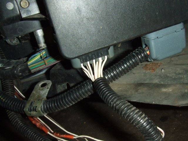

While the splices appear to be done properly I was told by the dealership that the entire harness needed to be replaced ($1200 part along with about $1200 for labor since the dash has to be taken out as the harness runs all the way to the back of the car). Well that is what they said...and what my insurance company was charged for (I still have my receipt). So I had a guy from my insurance come by today, take pictures, etc. and the dealership is trying to convince them that that is all part of the normal repair procedure. WTF? I can see that it CAN be a repair but splicing some wires together for an hour isn't quite the same as replacing the whole harness for almost $2500.
If anyone has some insight on this or suggestions how to handle this then please chime in. It may be a few days before the dealership can "look into it" but in the mean time I'd like some opinions. This "repair" was done over 5 years ago so that is my biggest hurdle.
Please see this link to my problems along with back story. But this post is about the harness so I'll explain more here.
My issue is that I finally pulled my fender off to look for a loose connection. And the entire wiring harness going into the TAC module is spliced together. Note that all the wires are white.
While the splices appear to be done properly I was told by the dealership that the entire harness needed to be replaced ($1200 part along with about $1200 for labor since the dash has to be taken out as the harness runs all the way to the back of the car). Well that is what they said...and what my insurance company was charged for (I still have my receipt). So I had a guy from my insurance come by today, take pictures, etc. and the dealership is trying to convince them that that is all part of the normal repair procedure. WTF? I can see that it CAN be a repair but splicing some wires together for an hour isn't quite the same as replacing the whole harness for almost $2500.
If anyone has some insight on this or suggestions how to handle this then please chime in. It may be a few days before the dealership can "look into it" but in the mean time I'd like some opinions. This "repair" was done over 5 years ago so that is my biggest hurdle.
 05-01-2009, 04:32 PM
#2
Instructor
Thread Starter
Oh...and if anyone has a diagram of where the TAC module wiring harness goes then that would be helpful. Or if part number 15329391 plugs directly into the TAC (as this is the part that was supposed to be replaced).
05-01-2009, 04:42 PM
#3
Le Mans Master

Member Since: Sep 2003
Location: Farmington CT
Posts: 6,126
Received 160 Likes
on
125 Posts
Cruise-In VII Veteran

it's been awhile since I did a motor swap, but I believe the harness runs behind the heads and into the pass footwell area, either way not likely needed to be swapped
I would re-pin that conn. and verify the colors are correct
could've have taken a batt acid bath at one point too, but looking at that Torx fastener seems someone has been in there(7mm head hex screw is GM)
I would re-pin that conn. and verify the colors are correct
could've have taken a batt acid bath at one point too, but looking at that Torx fastener seems someone has been in there(7mm head hex screw is GM)
05-01-2009, 07:24 PM
#4
Melting Slicks

Member Since: Oct 2007
Location: Kinston North Carolina
Posts: 2,382
Likes: 0
Received 9 Likes
on
9 Posts

Have you been driving this car for 5 years? If so, it's possible that might not be the problem. Looks like someone should check the codes and post them here. Also describe the symptoms of the problem you're haveing.
OK, I see the codes in the other post.
P1125 Accelerator Pedal Position (APP) System
P1286 Accelerator Pedal Position (APP) Sensor 3 Performance
C1241 Magnasteer Malfunction
C1278 TCS Temporarily Inhibited By PCM
U1064 Lost Communications with BCM
What year is it, I'll find you a schematic.
OK, I see the codes in the other post.
P1125 Accelerator Pedal Position (APP) System
P1286 Accelerator Pedal Position (APP) Sensor 3 Performance
C1241 Magnasteer Malfunction
C1278 TCS Temporarily Inhibited By PCM
U1064 Lost Communications with BCM
What year is it, I'll find you a schematic.
Last edited by byronhunter; 05-01-2009 at 07:40 PM.
 05-01-2009, 08:15 PM
#6
Melting Slicks
Member Since: Oct 2007
Location: Kinston North Carolina
Posts: 2,382
Likes: 0
Received 9 Likes
on
9 Posts
Also from '02 Service Manual:
DTC P1125
Circuit Description
The accelerator pedal position (APP) sensor is mounted on the accelerator pedal assembly. The sensor is actually 3 individual APP sensors within 1 housing. 3 separate signal, low reference, and 5-volt reference circuits are used in order to connect the accelerator pedal sensor assembly and the throttle actuator control (TAC) module. If only one APP sensor DTC is set, the redundant APP systems allow the TAC system to continue operating normally. This DTC sets if the powertrain control module (PCM) detects a condition with more than one APP sensor. One APP sensor DTC will not cause the Reduced Engine Power message to be displayed. 2 APP sensor DTCs for the same sensor also will not cause the Reduced Engine Power message to be displayed. However, if two or more DTCs are set involving more than 1 APP sensor, this DTC will set and the Reduced Engine Power message is displayed.
Conditions for Running the DTC
DTCs P1517, or P1518 are not set.
The ignition switch is in the crank or run position.
The ignition voltage is greater than 5.23 volts.
Conditions for Setting the DTC
Two or more APP sensors are out of range, all 3 APP sensors disagree, or 1 APP sensor is out of range and the other 2 APP sensors disagree.
All of the above conditions present for less than 1 second.
Action Taken When the DTC Sets
The control module illuminates the malfunction indicator lamp (MIL) when the diagnostic runs and fails.
The control module records the operating conditions at the time the diagnostic fails. The control module stores this information in the Freeze Frame and/or the Failure Records.
The control module commands the TAC system to operate in the Reduced Engine Power mode.
A message center or an indicator displays Reduced Engine Power.
Under certain conditions the control module commands the engine OFF.
Conditions for Clearing the MIL/DTC
The control module turns OFF the malfunction indicator lamp (MIL) after 3 consecutive ignition cycles that the diagnostic runs and does not fail.
A current DTC, Last Test Failed, clears when the diagnostic runs and passes.
A history DTC clears after 40 consecutive warm-up cycles, if no failures are reported by this or any other emission related diagnostic.
Clear the MIL and the DTC with a scan tool.
Diagnostic Aids
Inspect the TAC module connectors for signs of water intrusion. When water intrusion occurs, multiple DTCs could be set with no DTC circuit or component conditions found during diagnostic testing.
The APP sensor 1 and the TP sensor 1, 5-volt reference circuits are internally connected within the TAC module.
The APP sensor 2 and the TP sensor 2, 5-volt reference circuits are internally connected within the TAC module.
When the TAC module detects a condition within the TAC system, more than 1 TAC System related DTC may set. This is due to the many redundant tests that run continuously on this system. Locating and repairing 1 individual condition may correct more than 1 DTC. Keep this in mind when reviewing captured DTC info.
For an intermittent, refer to Intermittent Conditions .
DTC P1286
Circuit Description
The accelerator pedal position (APP) sensor is mounted on the accelerator pedal assembly. The sensor is actually 3 individual APP sensors within 1 housing. Three separate signal, low reference and 5-volt reference circuits connect the APP sensor assembly and the throttle actuator control (TAC) module. Each sensor has a unique functionality. The APP sensor 1 signal increases as the accelerator pedal is depressed, from below 1 volt at 0 percent pedal travel, with the pedal at rest, to above 2 volts at 100 percent pedal travel, with the pedal fully depressed. The APP sensor 2 signal decreases from above 4 volts at 0 percent pedal travel to below 2.9 volts at 100 percent pedal travel. The APP sensor 3 signal decreases from around 3.8 volts at 0 percent pedal travel to below 3.1 volts at 100 percent pedal travel. Notice that the signal circuits for APP sensor 2 and APP sensor 3 pull up to 5-volts and the APP sensor 1 signal circuit is referenced to low reference within the TAC module.
Conditions for Running the DTC
DTCs P0606, P1517, or P1518 are not set.
The ignition switch is in the crank or run position.
The ignition voltage is greater than 5.23 volts.
Conditions for Setting the DTC
APP sensor 3 disagrees with APP sensor 1 by more than 13 percent and APP sensor 3 disagrees with APP sensor 2 by more than 13 percent.
All of the above conditions are present for less than 1 second.
Action Taken When the DTC Sets
The control module stores the DTC information into memory when the diagnostic runs and fails.
The malfunction indicator lamp (MIL) will not illuminate.
The control module records the operating conditions at the time the diagnostic fails. The control module stores this information in the Failure Records.
If one or more APP sensor DTCs are set for a single APP sensor, the following occurs:
The control module will not command Reduced Engine Power mode.
The control module will use the remaining two APP sensors to calculate throttle response.
If certain multiple APP sensor DTCs are set for more than one APP sensor, the following occurs:
The control module commands Reduced Engine Power mode.
The APP indicated angle is limited to a predetermined value to limit the amount of throttle control.
The message center displays Reduced Engine Power.
If all three APP sensors are out of range, the following occurs:
The control module commands Reduced Engine Power mode.
The APP indicated angle is limited to 0 percent. The control module only allows the engine to idle.
The message center displays Reduced Engine Power.
Conditions for Clearing the DTC
A current DTC Last Test Failed clears when the diagnostic runs and passes.
A history DTC clears after 40 consecutive warm-up cycles, if no failures are reported by this or any other non-emission related diagnostic.
Clear the DTC with a scan tool.
Diagnostic Aids
Inspect the throttle actuator control (TAC) module connectors for signs of water intrusion. When water intrusion occurs, multiple DTCs could be set with no DTC circuit or component conditions found during diagnostic testing.
When the TAC module detects throttle movement with a DTC P1285 set, a DTC P1286 also sets.
When the TAC module detects a condition within the TAC system, more than 1 TAC system related DTC may set. This is due to the many redundant tests that run continuously on this system. Locating and repairing 1 individual condition may correct more than 1 DTC. Disconnecting components during testing may set additional DTCs. Keep this in mind when reviewing the stored information, Capture info.
For an intermittent, refer to Intermittent Conditions .
Test description
The numbers below refer to the step numbers in the diagnostic table.
This step determines if a communication condition exists.
This step isolates an internal APP sensor failure. The condition may only occur at a certain accelerator pedal position. Monitoring the APP angles for sensor 1 and sensor 2 is an accurate way of verifying the actual position of the pedal. The APP angles for all 3 sensors should be within a few percent of each other. When the pedal is at rest, the APP angle for all 3 sensors should be 0 percent. When the pedal is fully depressed, all APP angles should be 100 percent.
The APP sensor 3 has a dedicated 5-volt reference circuit. Monitoring the APP sensor 1 voltage aids in diagnosing the APP sensor 3 5-volt reference circuit. If the scan tool displays 5 volts then the circuits are OK.
When the TAC module detects a condition within the TAC system, more than 1 TAC system related DTC may set. This is due to the many redundant tests that run continuously on this system. Locating and repairing 1 individual condition may correct more than 1 DTC. Disconnecting components during testing may set additional DTCs. Keep this in mind when reviewing the stored information, Capture info.
05-02-2009, 11:47 AM
#7
Tech Contributor


Member Since: Dec 1999
Location: Anthony TX
Posts: 32,736
Received 2,180 Likes
on
1,583 Posts
CI 6,7,8,9,11 Vet
St. Jude Donor '08
If I were you,,,,I would take them to court and recoup the cost of the repairs (your deductible and give the rest back to the Insurance Co.
That splice repair is crappy to say the least. They should have used water proof splices if they had to use splices. My recommended repair method is to solder and use heat shrink.
If you paid for a wiring harness and the labor to replace it,,,,thats what you should have gotten.
Damn dealers. They think they have you bay the ***** and then do ****tey repair work.
PLEASE let us know how you make out.
05-11-2009, 01:11 AM
#8
Instructor
Thread Starter
Sorry for the delay....for some reason I have my notification sent to an email I don't ever use.
2001 Z06 is the car.
First off, my main reason for starting this thread was to try and verify that this is a repair that was supposed to be done. I have my receipt showing the wiring harness cost, price to replace the harness and price to removed and reinstall the dash (about $2500 to do it all). Even if I haven't been having problems for the past 5 years, this is a repair my insurance paid for and it wasn't done. So if part number 15329391 plugs directly into the TAC module then this should have been replaced; not spliced. This harness was damaged during the wreck and was not damage by acid before or after the repair.
With that being said I have been driving the car for 5 years since the accident with issues that started about a year later. I had it in for repairs and explained the problem and they suggested the TAC module needed to be replaced. I had it replaced (supposedly). While it could be a huge coincidence, I sure find it funny that there are splices 6 inches from the module that it goes into. The car drove fine for a year or so after that without issues. Then it all started happening again. But it happens so random that it is hard to track down. Sometimes it won't happen for months, while other times it will happen 20 different times while trying to limp home.
Right now I have cleared the codes and it is sitting in my garage. But one code won't clear (actually reappears) even without driving and that is code U1064. I'm sure a quick spin around the block would bring more codes back and then as soon as the "reduced power" mode hits a ton more would show up.
Taking them to court is an option but it is kind of complicated since my insurance is stating it is really up to the dealer if they want to make things right. It seems that they really don't care that they were ripped off is the sad part. If I can possibly track down the problem and fix this myself it would be ideal (since it probably STILL wouldn't get fixed properly). Plus I have a feeling if I end up back at the dealership I am leaving in a cop car since I am so irate over this whole deal.
05-11-2009, 06:47 AM
#9
Burning Brakes

Member Since: Oct 2003
Location: Foresters Falls(near Ottawa) Ont
Posts: 1,106
Likes: 0
Received 1 Like
on
1 Post
My TAC module harness terminal failed when I was 12 hours from home, it put me into the "limp in" mode. Had it repaired at a Chev dealer ( That was a three day wait!!) and when I got home I found EFI Connection.
http://www.eficonnection.com/eficonn...omponents.aspx
These folks provided me with a pre-wired 16 way TAC pig tail, something that GM doesn't sell and the price was very reasonable.
RonJ ...
http://www.eficonnection.com/eficonn...omponents.aspx
These folks provided me with a pre-wired 16 way TAC pig tail, something that GM doesn't sell and the price was very reasonable.
RonJ ...
05-11-2009, 09:01 PM
#10
Instructor
Thread Starter
That's awesome RonJ! For $40 I may just replace the harness that runs between the TAC and the pedal....assuming I can find a hole to get the plug through the firewall.
Last edited by IsItFast; 05-12-2009 at 02:04 AM.
06-09-2009, 01:31 PM
#11
Pro

Member Since: Jun 2008
Location: Philly region SCCA
Posts: 583
Likes: 0
Received 0 Likes
on
0 Posts

I'm having a similar problem. Getting the accelerator pedal position codes and corresponding reduced engine power message.
Car is at the dealership now but they can't reproduce the problem after I somehow managed to get it cleared and drive it to them.
I'd like to check the wiring on my own but can't find a diagram of where the pedal wires lead to the TAC module. Can anyone post one?
Car is at the dealership now but they can't reproduce the problem after I somehow managed to get it cleared and drive it to them.
I'd like to check the wiring on my own but can't find a diagram of where the pedal wires lead to the TAC module. Can anyone post one?
06-09-2009, 02:53 PM
#12
Instructor
Thread Starter
Well in the image above, the harness that goes into the left of the box is the part of the harness that runs directly to the pedal. All of my wires in the image are white but your should be multicolored.
I ended up purchasing a harness from eficonnections for $40 that simply plugged in between the module and the pedal, bypassing the factory harness. So far so go (fingers crossed).
In your case, unless your wires are damaged, I would mainly check the connectors to make sure all the tabs within them are still tight and not corroded. But it is quite typical for battery acid to leak down on those wires and damage them. To check: Take off the passenger front wheel and remove the service panel in the fender well. I found it easier to remove most of the fender bolts too so I could pull it away from the car (though still attached).
06-09-2009, 02:55 PM
#13
Pro
Member Since: Jun 2008
Location: Philly region SCCA
Posts: 583
Likes: 0
Received 0 Likes
on
0 Posts
I guess what I should have said was that I don't know where to look in the car to find the box that all those wires run to. I have the wiring diagrams available.
Looks like in the passenger fender...thanks.
Looks like in the passenger fender...thanks.
03-22-2010, 10:10 PM
#14
Instructor
Thread Starter
Just for reference, I never had a problem again after replacing the wiring harness so that must have been the problem. Sadly, I only had the car for 6 months after fixing it...but dealt with the problem for 5 years.

