
C5 Ignition Switch Repair
 02-26-2008, 02:05 AM
#1
Tech Contributor


Thread Starter

Member Since: Dec 1999
Location: Anthony TX
Posts: 32,735
Received 2,180 Likes
on
1,583 Posts
CI 6,7,8,9,11 Vet
St. Jude Donor '08

C5 Ignition Switch Repair
by Bill Curlee
There have been quite a few forum members with IGNITION SWITCH failure. There are a number of different symptoms to indicate that the switch is bad.
I helped FASTVETZO6 ( Mark) troubleshoot his problem down to the ignition switch. After replacement of the ignition switch, his problems were resolved. He mailed his old switch to me and I have dissected it, figured out why they fail and detailed the switch repair!
Thanks for the switch Mark! You made my weekend!
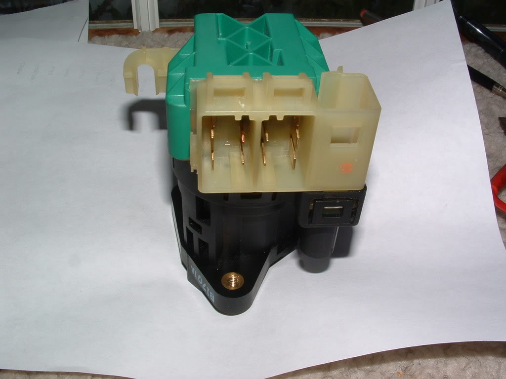
Here is the switch removed from the car The ignition lock cylinder has been removed. This is how you will receive the new switch from GM:
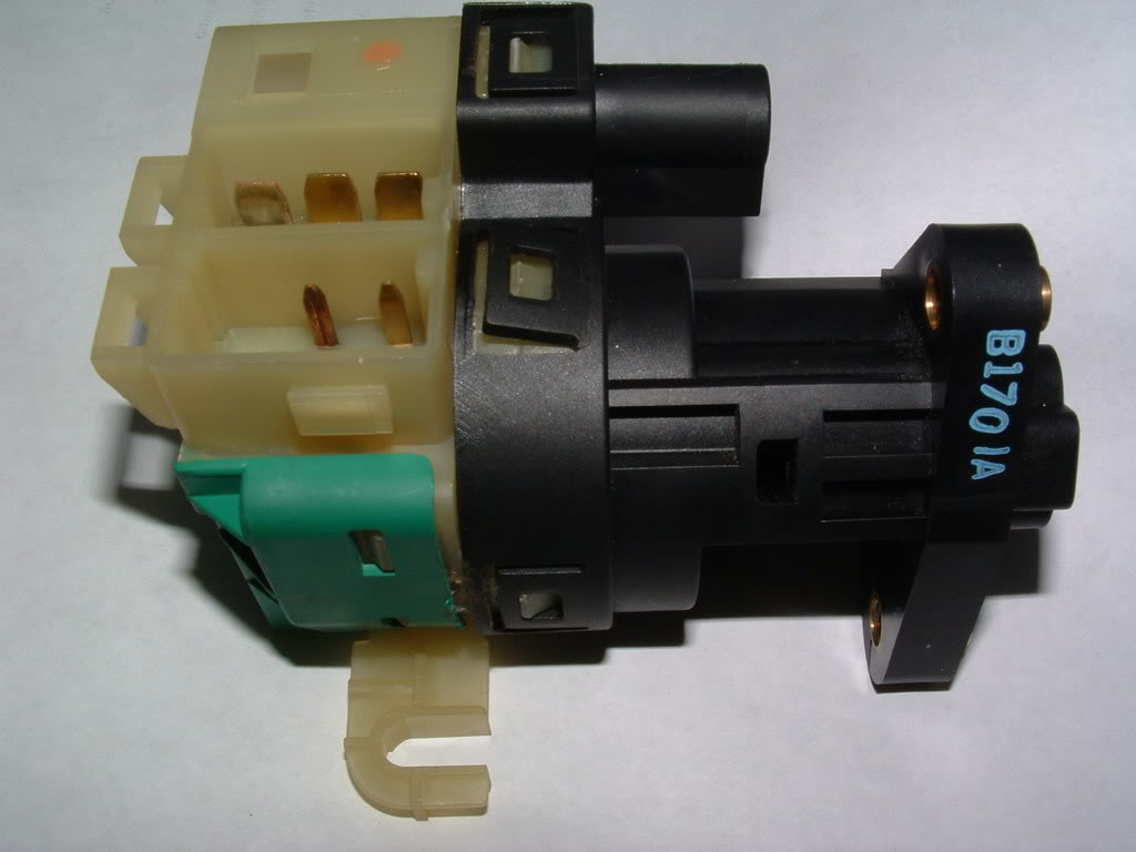
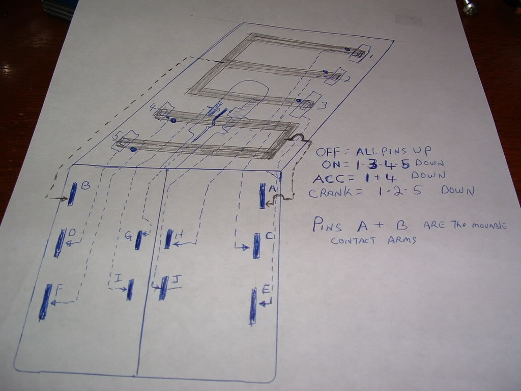
Looks complicated but its really very simple. The first step is to use an ohm meter to see if the switch is really bad before disassembly. I have included a hand drawn schematic of the switch PLEASE excuse the roughness of the drawing.
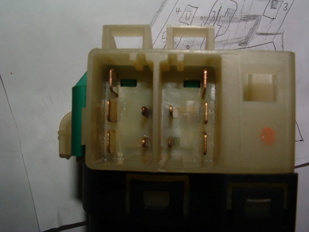
Use an ohm meter and ohm out each contact. You will need to cycle the switch through OFF, ACC, ON and Crank. Each contact point should be 0-1 ohms. Marks switch was reading 2500 + ohms on contacts 5 & D and 2000 ohms on contacts 3 & E.
( NOTE! The contact letters and numbers do NOT correspond to the C5 schematics. I added my own letters and numbers to help explain the drawing!
The switch contacts in the center area of the switch are the contacts that tell the BCM if the ignition KEY is inserted in the ignition cylinder or not.
Once you determine that the contacts are good or bad, remove the top GREEN cover to expose the switch contacts. The cover is easily removed by prying up the tabs "evenly" with a screwdriver.
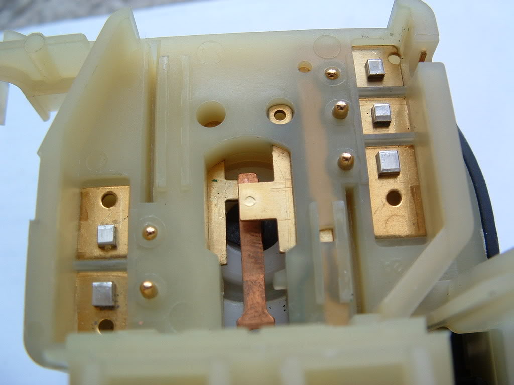
Once the cover is off, this is what you will see:
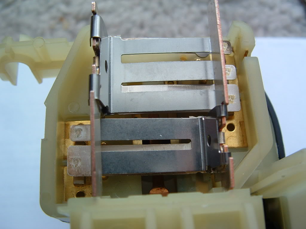
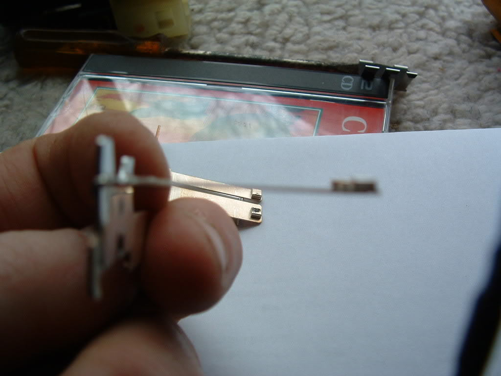
Lift out the movable contact strips noting how the movable contacts and springs on top of the contact arms are assembled. The springs can and will fall off the arms!
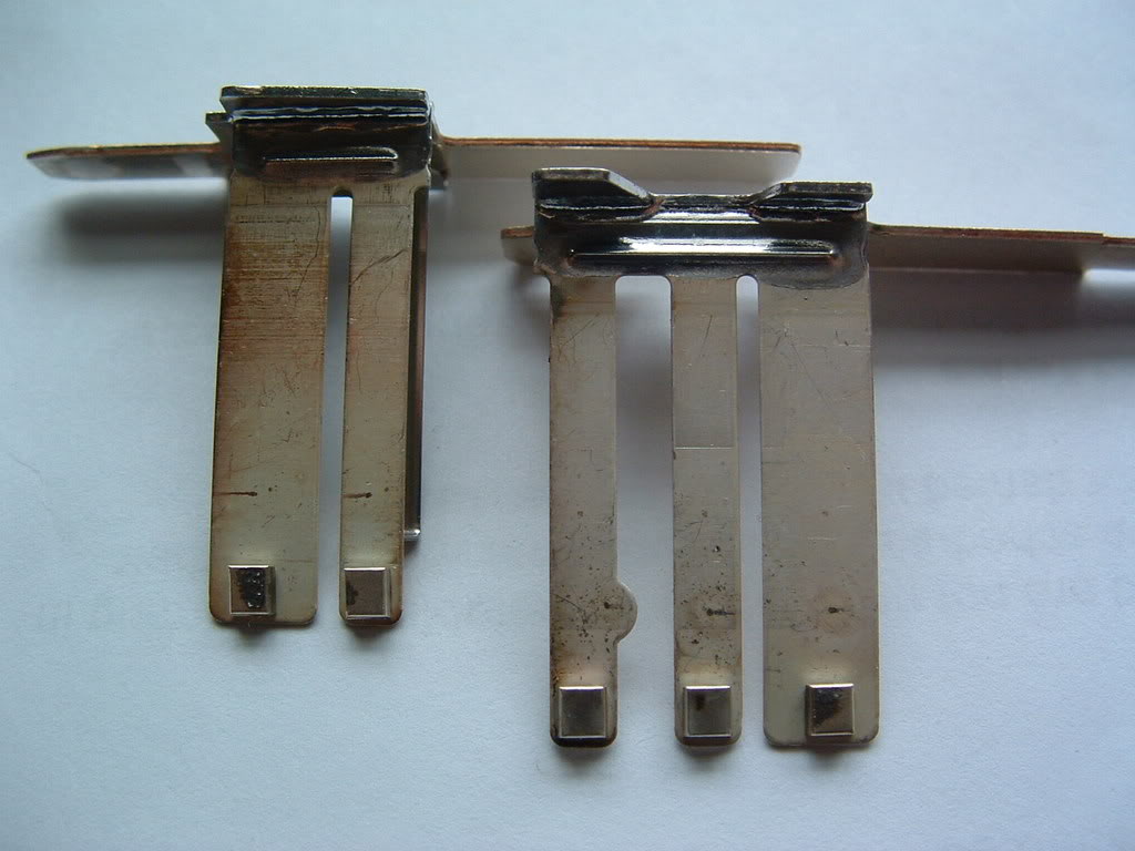
Once the contacts are out, this is what you will see:
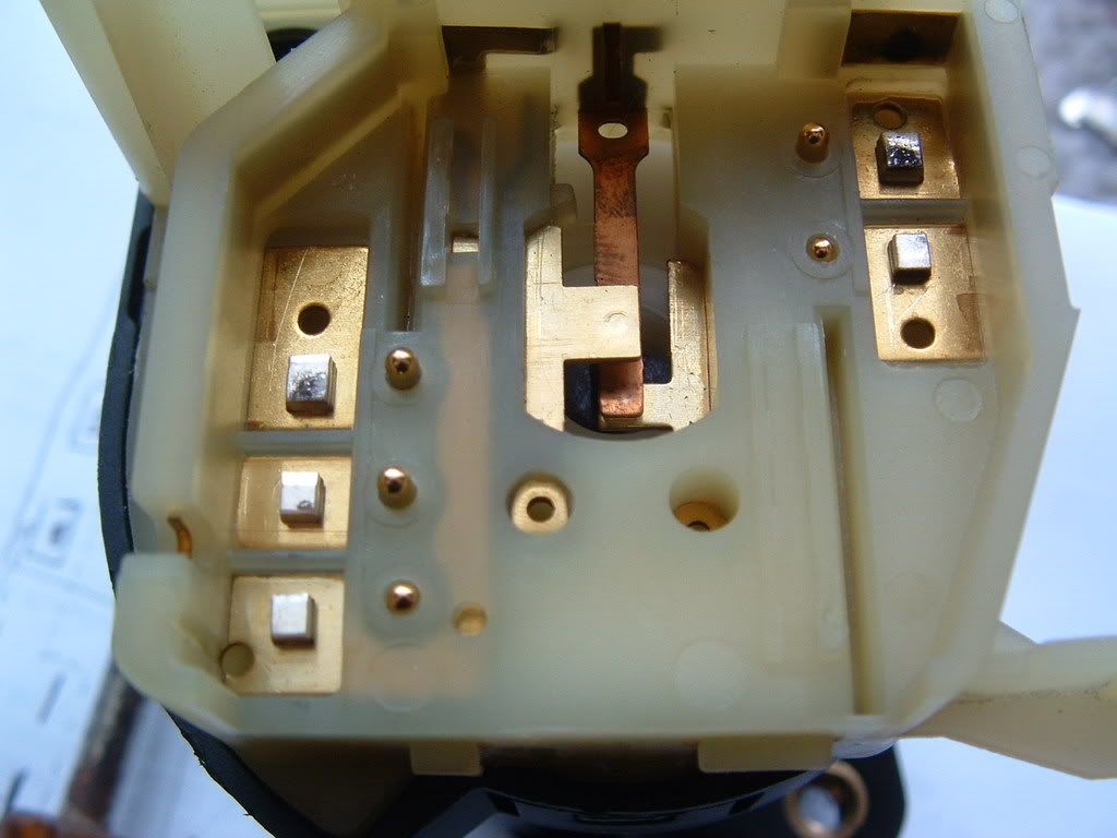
In Marks switch you can see TWO distinct burnt contacts. Those were the bad contacts.
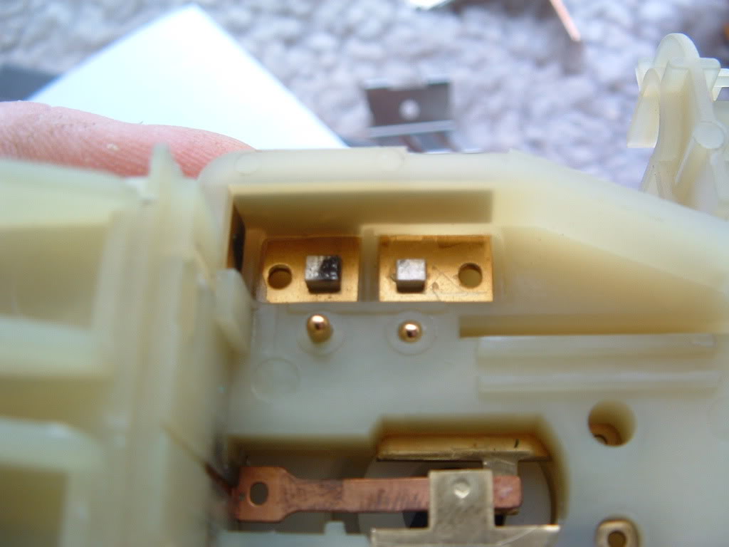
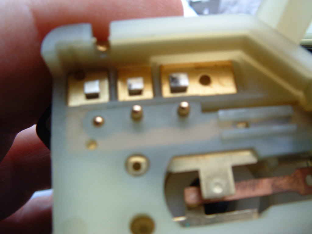
The small brass pins just inside the fixed contacts are the pins that move UP & DOWN to operate the contacts.
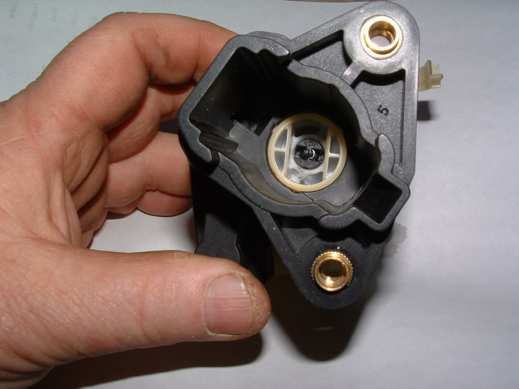
The section of the switch below the section shown in the pictures above only contains the cam to move the brass pins UP & DOWN to operate the movable switch arms and contain NO electrical contacts. There is no need to disassemble this portion of the switch. When you rotate the switch the brass contacts will move UP or DOWN with each position of the switch.
There is a legend next to the hand drawn schematic that explains how the pins operate when the switch is moved through the various positions of the ignition switch.
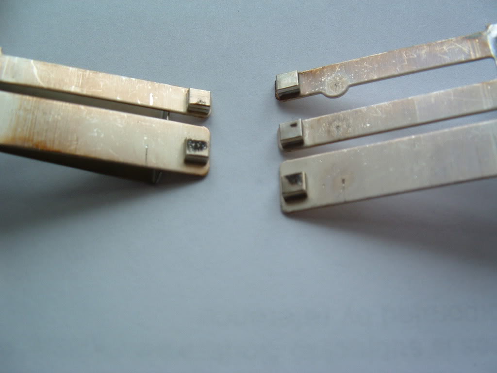
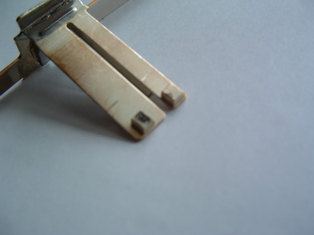
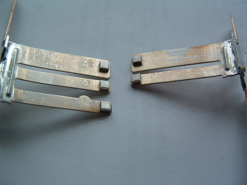
I believe that the movable contact arms loose spring tension and cause poor contact and that results in contact arcing. Here is what the arms looked like when removed. The arm is slightly bent back wards:
Here is the burnt contacts on the arms:
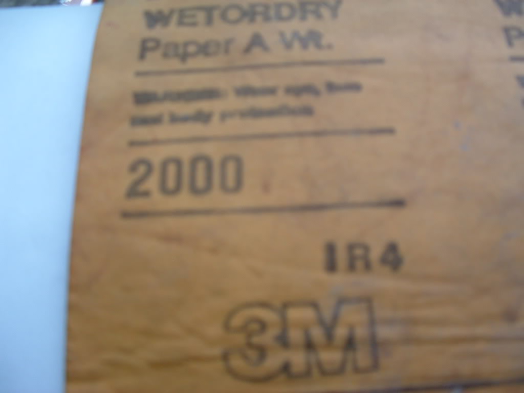
I used 2000 grit wet & dry sand paper to clean the fixed and movable contacts. Polish the contacts clean to remove carbon and pitting.
Once there polished clean, wipe them down with alcohol.
(Part 2 continued in next post)
by Bill Curlee
There have been quite a few forum members with IGNITION SWITCH failure. There are a number of different symptoms to indicate that the switch is bad.
I helped FASTVETZO6 ( Mark) troubleshoot his problem down to the ignition switch. After replacement of the ignition switch, his problems were resolved. He mailed his old switch to me and I have dissected it, figured out why they fail and detailed the switch repair!
Thanks for the switch Mark! You made my weekend!
Here is the switch removed from the car The ignition lock cylinder has been removed. This is how you will receive the new switch from GM:
Looks complicated but its really very simple. The first step is to use an ohm meter to see if the switch is really bad before disassembly. I have included a hand drawn schematic of the switch PLEASE excuse the roughness of the drawing.
Use an ohm meter and ohm out each contact. You will need to cycle the switch through OFF, ACC, ON and Crank. Each contact point should be 0-1 ohms. Marks switch was reading 2500 + ohms on contacts 5 & D and 2000 ohms on contacts 3 & E.
( NOTE! The contact letters and numbers do NOT correspond to the C5 schematics. I added my own letters and numbers to help explain the drawing!
The switch contacts in the center area of the switch are the contacts that tell the BCM if the ignition KEY is inserted in the ignition cylinder or not.
Once you determine that the contacts are good or bad, remove the top GREEN cover to expose the switch contacts. The cover is easily removed by prying up the tabs "evenly" with a screwdriver.
Once the cover is off, this is what you will see:
Lift out the movable contact strips noting how the movable contacts and springs on top of the contact arms are assembled. The springs can and will fall off the arms!
Once the contacts are out, this is what you will see:
In Marks switch you can see TWO distinct burnt contacts. Those were the bad contacts.
The small brass pins just inside the fixed contacts are the pins that move UP & DOWN to operate the contacts.
The section of the switch below the section shown in the pictures above only contains the cam to move the brass pins UP & DOWN to operate the movable switch arms and contain NO electrical contacts. There is no need to disassemble this portion of the switch. When you rotate the switch the brass contacts will move UP or DOWN with each position of the switch.
There is a legend next to the hand drawn schematic that explains how the pins operate when the switch is moved through the various positions of the ignition switch.
I believe that the movable contact arms loose spring tension and cause poor contact and that results in contact arcing. Here is what the arms looked like when removed. The arm is slightly bent back wards:
Here is the burnt contacts on the arms:
I used 2000 grit wet & dry sand paper to clean the fixed and movable contacts. Polish the contacts clean to remove carbon and pitting.
Once there polished clean, wipe them down with alcohol.
(Part 2 continued in next post)
Last edited by Bill Curlee; 07-30-2013 at 05:45 AM.

The following 2 users liked this post by Bill Curlee:
CorvetteBrent (09-12-2018),
Tron Z (11-20-2023)

Popular Reply
02-26-2008, 02:05 AM
Tech Contributor
Thread Starter
Member Since: Dec 1999
Location: Anthony TX
Posts: 32,735
Received 2,180 Likes
on
1,583 Posts
CI 6,7,8,9,11 Vet
St. Jude Donor '08
Here are all the contacts cleaned up:
I used a mechanical pencil with sand paper glued to the eraser to clean the fixed contacts. The eraser was trimmed down to fit the recess in the switch housing:

Once the contacts are cleaned up, bend the contact arms so that they apply more tension on the fixed contacts. It doesn't need too much bending:
Once you apply more tension to the contacts, you will need to be careful when reinserting the arms back into the switch. The movable contact pads will tend to hang up on the fixed contacts. Assist them over the fixed contacts. I used a hooked paper clip to raise the arm over the fixed contact.
I used two flat blade screwdrivers to apply force to contacts A & B inside the switch contact well to keep the contact arms forced down on the fixed contacts to prevent them from popping out of place while installing the green cap. Once the contacts are in place,

snap the green cap back on the switch. Check the CLEANED contacts with an ohm meter. They should read very close to ZERO OHMS.
Please feel free to ask me any questions that you have. I feel I'm a IGNITION SWITCH expert now!
Marks old NASTY broken switch is as good as new!!!!!!!!!!


* NOTE!!!!! UP_DATED 10 Sep 2012:
Some DO's and DONT's
1. It is NOT necessary to disassemble the lower portion of the switch!! There is NOTHING in there electrical related!
2. Electrical contact cleaning: Deeply pitted contacts can be cleaned using 400 Wet & Dry paper but should be polished with finer & finer grits to a highly polished surface 400, 600, 800 1000 grit wet & dry paper and cleaned with alcohol when done polishing. If there not deeply pitted start with 800 grit. It is strongly recommended to assemble the switch contact arms and place sand paper between the contacts. Apply force on the movable contact arm and pull the sand paper THRU the contacts. This will seat the upper and lower contacts and put a larger contact patch on the contacts. The larger the contact patch on the switch contacts allow the contacts to pass higher currents before over heating!
3. Measure the repaired contacts with an OHM METER before reassembly!! If you dont have ZERO ohms, figure out why and fix it! Make sure that the OHM Meter is on the ohms X1 Scale or in auto mode and your really are reading ONE OHM or less. Cycle the switch several times and make sure you get constant good resistance readings!
4. When you insert the key into the switch lock tumbler, the end of the key pushes on the small button on the center of the tumbler well. Its important that you test the operation of that switch as it tells the BCM when the key is in or out of the switch/tumbler.
5. On the front of the tumbler is a small sensor. Inside that sensor are two small silver coated contacts. Those contacts read the resistor pellet embeded in your key. Measure the pellet in your key. insert the key into the sensor and measure the output of the sensor with the key in it. The two readings should match. If they dont the sensor contacts are dirty or damaged.
BC
Heres the procedure for removing the ignition switch from the dash:
Ignition Switch Replacement
Removal Procedure
Caution
Before servicing any electrical component, the ignition key must be in the OFF or LOCK position and all electrical loads must be OFF, unless instructed otherwise in these procedures. If a tool or equipment could easily come in contact with a live exposed electrical terminal, also disconnect the negative battery cable. Failure to follow these precautions may cause personal injury and/or damage to the vehicle or its components.
Disconnect the negative battery cable.
Apply the parking brake.
Remove the console. Refer to Compartment Replacement - Instrument Panel (I/P) .
+++++++++++++++++++++++++++++++++
--------------------------------------------------------------------------------
Compartment Replacement - Instrument Panel (I/P)
Removal Procedure
Open the instrument panel (I/P) passenger compartment door.
Disconnect the electrical connector from the I/P compartment lamp switch.
Remove the trim plugs from the bottom of the compartment door. Reach behind the compartment door and push the plugs out. Use a suitable flat bladed tool on the front side to remove the plugs, if necessary.
Remove the lower retaining bolts from the I/P compartment.
Remove the side and upper retaining screws from the I/P compartment.
Slowly pull the I/P compartment just enough to disconnect the wiring harness connector from the inflatable restraint module switch.
Remove the I/P compartment.
Installation Procedure
Connect the wiring harness connector to the inflatable restraint I/P module switch connector.
Install the I/P compartment.
Loosely install the screw which retains the side of the I/P compartment, in order to align the nut on the passenger SIR bracket.
Notice
Use the correct fastener in the correct location. Replacement fasteners must be the correct part number for that application. Fasteners requiring replacement or fasteners requiring the use of thread locking compound or sealant are identified in the service procedure. Do not use paints, lubricants, or corrosion inhibitors on fasteners or fastener joint surfaces unless specified. These coatings affect fastener torque and joint clamping force and may damage the fastener. Use the correct tightening sequence and specifications when installing fasteners in order to avoid damage to parts and systems.
Install the upper retaining screw to the I/P compartment. Tighten
Tighten the retaining screw to 1.9 N�m (17 lb in).
Install the lower retaining bolts to the I/P compartment. Tighten
Tighten the retaining bolts to 12 N�m (106 lb in).
Align and hold the I/P compartment to the I/P, then install the side retaining screw to the I/P compartment. Tighten
Tighten the retaining screw to 1.9 N�m (17 lb in).
Install the trim plugs to the I/P compartment door.
Connect the electrical connector to the I/P compartment lamp switch.
Close the I/P passenger compartment door.
++++++++++++++++++++++++++++++++++
Remove the IP accessory trim plate. Refer to Trim Plate Replacement - Instrument Panel (I/P) Accessory .
++++++++++++++++++++++++++++++++++
Trim Plate Replacement - Instrument Panel (I/P) Accessory
Removal Procedure
Apply the parking brake for additional clearance around the parking brake lever.
Shift the transmission into SECOND (A/T), or FOURTH (M/T).
Remove the console. Refer to Console Replacement .
Grasp the shift control boot (M/T) and apply light pressure in toward the shift control lever, to begin to release the shift boot retaining tabs from the instrument panel (IP) accessory trim plate.
Using light pressure, continue to release the remaining boot retaining tabs, then lift the boot away from the trim plate.
Open the cigar lighter door and remove the ashtray.
Remove the IP accessory trim plate grille. Pry gently at the side edge with a flat-bladed screwdriver to release the tab.
Remove the accessory trim plate retaining screws next to the cigar lighter and behind the ashtray.
Remove the accessory trim plate retaining screw in the grille opening.
Grasp the sides of the accessory trim plate near the curve at the base.
Pull the trim plate rearward to release the locking tabs. Lift the rear of the trim plate to clear the driveline tunnel studs.
Disconnect the electrical connector from the cigar lighter.
Rotate the shift control boot (M/T) and reposition one end down into the shifter opening in the trim plate.
Lift the accessory trim plate over the shifter (and shift control boot, M/T), and remove the trim plate.
Installation Procedure
Lower the IP accessory trim plate over the shifter and under the parking brake lever. Position the shift control boot (M/T) as during removal and insert the boot up through the shifter opening in the accessory trim plate.
Connect the electrical connector to the cigar lighter.
Install the trim plate into position. Align the locator tabs and the locking tabs to the slots.
Begin to install the upper locator tabs and the upper locking tabs, then work downward to install the remaining tabs. Install the rear of the trim plate onto the driveline tunnel studs.
Notice
Use the correct fastener in the correct location. Replacement fasteners must be the correct part number for that application. Fasteners requiring replacement or fasteners requiring the use of thread locking compound or sealant are identified in the service procedure. Do not use paints, lubricants, or corrosion inhibitors on fasteners or fastener joint surfaces unless specified. These coatings affect fastener torque and joint clamping force and may damage the fastener. Use the correct tightening sequence and specifications when installing fasteners in order to avoid damage to parts and systems.
Install the accessory trim plate retaining screws. Tighten
Tighten the IP accessory trim plate retaining screw next to cigar lighter to 1.9 N�m (17 lb in).
Tighten the IP accessory trim plate retaining screw behind ashtray to 1.9 N�m (17 lb in).
Tighten the IP accessory trim plate retaining screw in grille opening to 1.9 N�m (17 lb in).
Install the accessory trim plate grille. Position the grille, then push to secure.
Install the ashtray.
Install the console. Refer to Console Replacement .
Align the shift control boot to the IP accessory trim plate opening, then press to lock the boot retaining tabs.
Adjust the shape of the boot for appearance, if necessary.
Shift the transmission into PARK (A/T), or REVERSE (M/T).
Release the parking brake.
++++++++++++++++++++++++++++++++++
Remove the driver knee bolster trim panel. Refer to Trim Panel Replacement - Knee Bolster .
+++++++++++++++++++++++++++++++++
Trim Panel Replacement - Knee Bolster
Removal Procedure
Remove the console. Refer to Console Replacement .
Remove the IP accessory trim plate. Refer to Trim Plate Replacement - Instrument Panel (I/P) Accessory .
Remove the fog lamp, rear compartment lid release switch.
Pry carefully at the lower edge of the switch to release the locking tab.
Disconnect the electrical connector from the switch.
Remove the driver knee bolster trim panel retaining screw behind the fog lamp, rear compartment lid release switch.
Remove the driver knee bolster trim panel lower retaining screws.
Grasp the trim panel at the side edges.
Pull firmly rearward to release the locking tabs.
Disconnect the electrical connector from the inside air temperature sensor, if equipped.
Remove the trim panel.
Installation Procedure
Connect the electrical connector to the inside air temperature sensor, if equipped.
Insert the electrical connector for the fog lamp, rear compartment lid release switch through the opening in the trim panel.
Install the driver knee bolster trim panel.
If equipped, insert the inside air temperature sensor wire down into the driver knee bolster bracket to avoid pinching the wire.
Align the locking tabs to the slots.
Push the trim panel to secure.
Loosely install the screws retaining the bottom of the driver knee bolster trim panel, in order to align the nuts on the knee bolster bracket.
Notice
Use the correct fastener in the correct location. Replacement fasteners must be the correct part number for that application. Fasteners requiring replacement or fasteners requiring the use of thread locking compound or sealant are identified in the service procedure. Do not use paints, lubricants, or corrosion inhibitors on fasteners or fastener joint surfaces unless specified. These coatings affect fastener torque and joint clamping force and may damage the fastener. Use the correct tightening sequence and specifications when installing fasteners in order to avoid damage to parts and systems.
Install the remaining driver knee bolster trim panel retaining screw. Tighten
Tighten the driver knee bolster trim panel retaining screw behind fog lamp, rear compartment lid release switch to 1.8 N�m (16 lb in).
Tighten the driver knee bolster trim panel lower retaining screws to 1.8 N�m (16 lb in).
Install the fog lamp, rear compartment lid release switch.
Connect the electrical connector to the switch.
Align the switch, then push to secure.
Install the IP accessory trim plate. Refer to Trim Plate Replacement - Instrument Panel (I/P) Accessory .
Install the console. Refer to Console Replacement .
+++++++++++++++++++++++++++++++++
Remove the ignition switch lock cylinder electrical connector from the retaining tab on the side of the ignition switch.
Disconnect the lock cylinder electrical connector.
Important
Take note of the way in which the ignition switch lock cylinder wire is wrapped around the base of the ignition switch bezel.
Remove the ignition switch bezel. Carefully pull to unsnap.
Remove the hazard warning switch wiring harness from the ignition switch retainer.
Disconnect the ignition switch electrical connectors.
Disconnect the park/lock cable (A/T) from the ignition switch.
Insert the key into the ignition switch, then turn the ignition to ON.
Using a flat bladed screwdriver or other suitable tool, depress the park/lock cable retaining tab (located on the underside of the switch near the base of the cable).
Pull to remove the cable.
Remove the ignition switch retaining bolts.
Remove the ignition switch.
Installation Procedure
Install the ignition switch into position on the ignition switch housing bracket.
Notice
Use the correct fastener in the correct location. Replacement fasteners must be the correct part number for that application. Fasteners requiring replacement or fasteners requiring the use of thread locking compound or sealant are identified in the service procedure. Do not use paints, lubricants, or corrosion inhibitors on fasteners or fastener joint surfaces unless specified. These coatings affect fastener torque and joint clamping force and may damage the fastener. Use the correct tightening sequence and specifications when installing fasteners in order to avoid damage to parts and systems.
Install the ignition switch retaining bolts. Tighten
Tighten the ignition switch retaining bolts to 5.5 N�m (49 lb in).
Install the park/lock cable (A/T) to the ignition switch (still in the ON position). Push to secure the cable retaining tab.
Connect the ignition switch electrical connections.
Install the hazard warning switch wiring harness to the ignition switch retainer.
Install the ignition switch bezel to the switch.
Wrap the ignition switch lock cylinder wire around the base of the ignition switch bezel, as noted during removal.
Align the bezel slots to the lock cylinder pins, then push to secure.
Connect the lock cylinder electrical connector.
Install the lock cylinder electrical connector to the retaining tab on the side of the ignition switch.
Install the driver knee bolster trim panel. Refer to Trim Panel Replacement - Knee Bolster .
Install the IP accessory trim plate. Refer to Trim Plate Replacement - Instrument Panel (I/P) Accessory .
Install the console. Refer to Compartment Replacement - Instrument Panel (I/P) .
Connect the negative battery cable. Tighten
Tighten the negative battery cable bolt to 15 N�m (11 lb ft).
Program the transmitters. Refer to Transmitter Programming/Synchronization in Keyless Entry.
Release the parking brake.
-----------------------------------------------------------------------------------------------------
If you "THINK" you have an ignition switch issue, you can use a volt meter and measure the output of the ignition switch.
There are TWO voltages that power the critical modules in our cars. One is "HOT AT ALL TIMES" and the other is "HOT in ACC and ON". When you turn the ignition switch to ON, you can read the fuses listed below and you should see exactly what the battery puts out. If the electrical contacts inside the switch are burnt, there will be resistance in the circuit and the voltage output of the switch will be lower or even zero.
On top of the fuses are two small holes that you can insert pin point meter leads into and read that fuse terminal. MAKE SURE to read both holes. If the fuse happens to be blown, only the battery side will have voltage on it.
Heres another troubleshooting tip: If you read across the fuse; If it good, you should read ZERO VOLTS! If its bad, you will read BATTERY VOLTAGE.
Heres the schematic for the START /Crank side of the switch:
Heres the schematic for the IPC and the voltage that you see on the IPC Volt Meter:

Here are the fuses powered by the "HOT in ACC and ON". part of the switch:
Ok,,,here are the fuses that your going to check:
Under Hood Fuse Center
ENG ING1 FUSE# 19
INJR 2 FUSE# 18
THROTCONT FUSE# 17
INJR 1 FUSE# 22
PCM FUSE# 16
F/PMP FUSE# 13
Instrument Panel Fuse block
BTSI BU Fuse# 21
BCM 13 Fuse# 22
IPC Fuse# 19
Check the VOLTAGE on these fuses when the ignition is in the ON position. There should be battery voltage on these fuses.
Another ignition switch troubleshooting aid is; If the engine will run when you HOLD the ignition switch to the CRANK position but dies when you release the key, the switch could be at fault.
SOME UP DATED Switch repair info Sep 2011:
Some additional guidance on the ignition switch repair.
Remember to re-arch the movable switch contacts so that they have better contact with the fixed contact point. Once there re-arched, you will need to use a hook (I used a bent paper clip) to ASSIST the arms over the FIXED contacts when your sliding them back into place!
Once the switch movable contact arms are in place, insert a piece of 600 grit wet and dry paper between the closed contacts and with a small pair of needle nose pliers or a pair of tweezers (I use a small pair of curved hemostats),, Move the sand paper between the contacts while applying some pressure on top of the movable arm. Switch to 1000 grit and polish the contacts. Clean the contacts with alcohol.
What your doing is making the CONTACT AREA of that single switch larger than it was. That will give the contact more current carrying ability and better contact. Do that to each of the FIVE switches....
REMEMBER!! Measure the resistance of EACH of the newly cleaned, re-arched, sanded and polished and cleaned contacts to make sure you have very very close to ZERO ohms resistance when the contacts are shut! If you have resistance, go back and CLEAN the contacts with alcohol again
Here are a FEW UPDATES that have been added as we refine this repair process:
Recommned that you obtain some 600 grit wet and dry sand paper. Cut a strip about 6" long X 3/4" wide. Fold it in half so that you have sand paper on both sides. Work the sand paper in between all the contacts on one side of the switch. Pull and push the sand paper between the stationary contacts and movable contact arms. Doing this will lap in a bigger contact area between the two contacts thus allowing the switch to carry a bigger current load without heating up. When you are done lapping the contacts on one side, lap the other side.
NOTE! Make sure that you recheck the contact pressure on the contach arms to insure that they are still making firm contact. Clean the contacts and recheck the resistance of each switch.
NOTE! The Electrical connectors with FEMALE PINS that pulg into the Ignition Switch can spread and male poor connection with the male pins inside the switch. Check the female pins inside the two power connectors:
Once you sand the burned marks off the bent female pins, rebend them back so that the tong makes better contact with the male pins inside the switch. There are TWO damaged large pins in the black plug and one on the white plug.
Bill
Update 24 May 13
I have to admit that; just because the ignition switch contacts look burnt, they still could be fine. The problem occurs when the contacts start building resistance from the carbon, poor contact continuity and burnt contacts.
That excessive resistance causes the 12 VDC battery voltage supplied to the switch and controlled by those contacts to be something LESS than full battery voltage. If the switch is marginally defective, it may work one ignition sequence and fail horribly the next. Please check the ignition switch resistance AND electrical output after cycling it several times.
Most of the problems with our ignition switches are, the contacts do not close perfectly parallel and after thousands of OPEN/SHUT cycles, the contact arms heat up and loose tension. That�s when the resistance starts building and the switch contacts generate excessive heat and degraded voltage outputs.
Before any ignition switch is rebuilt/repaired, you should measure the closed contacts with an OHM Meter and see what you have resistance wise. Measuring all the contacts requires cycling the switch thru all of its available positions. Write down the resistance value before repair and then again after repair.
When you repair/rebuild the switch, re-arch the movable contact arms so that they shut with more pressure.
One of the reasons that the contacts get hot is, some circuits draw a moderate amounts of current. If the contacts don�t close perfectly parallel, there is only a very small contact point for the current to flow thru. That causes heat and excessive arching when the contacts shut.
Im going to reassemble a switch and slide some wet and dry sand paper between the closed contacts and work the paper between the contacts to LAP the contacts so that they have a larger contact point
NOTE! Anytime you clean/sand or file any electrical contact, you should finish the surface as smooth as you can and before finial reassembly, clean the contacts with isopropyl alcohol so that there is no grease or grit between the contacts.
As always, CHECK THE RESISTANCE of each contact in the switch (you have to cycle it thru all it positions) and make sure that it is not excessive. When you re-arch the movable arms, if you are TOO AGGRESSIVE, the switch contacts will never open when the arm is pushed open and that will cause an ignition circuit to remain ON when its suppose to be OFF. That will cause excessive battery current draw in the sleep mode and KILL the battery in short order.
Something else that needs to be examined is the female pins in the ignition switch connector. If they are spread and make poor contact, they also can cause lower ignition switch output voltages. I have seen female pin contacts so loose that they heat up and melt the connector causing ignition switch failure on all outputs for that 12 VDC circuit.
Look at the picture provided. Two of the contacts in the black connector (the two on the inboard contacts) are spread apart and have signs of electrical arcing and carbon. They need to be cleaned and the tong needs to be bent so that it makes better contact with the male pin inside the switch
I will add this to my Ignition Switch post.
HERE IS THE 99 c5 SCHEMATIC OF THE IGNITION SWITCH OUTPUT :
UPDATE 11 / 15/ 2023 IGNITION SWITCH CONNECTOR FEMALE PIN INSPECTION.
Along with ignition switch inspection repair and replacement, An Inspection shoule also be conducted on the TWO Car Harness Connectors that connect to the ignition switch. Over time, HEAT & Cold Cycles along with vibration causes the FEMALE PINS in all of our connectors to spread apart and make a poor connection with the associated MALE PIN inside the Ignition Switch.
If you have an ignition switch issue or your modules or the CAR just randomly shuts off, POOR CONNECTIONS inside the ignition switch connectors could be an issue.
Its a VERY COMMON ISSUE!
CONNECTOR INSPECTION:
- Disconnect the Negative battery terminal.
- Disconnect the Two Main Connectors that connect to the Ignition Switch.
- Inspect the Female Pins & The plastic wells that the pins fit into. Look for discoloration, Melted Plastic and pin deformation. The only war to absolutely insure that the female pins are not spread apart far enough to make a poor intermittent connection is to do a PIN PUSH PULL TEST. You need to find a spare male pin that is the exact same thickness as the male pin inside the Ignition Switch Connector Well.
I have used a Fuse to construct a TEST pin. Snap the Fuse inhalf. Use a file and sand paper to trim and shape the Fuse Spade pin to the correct thickness and width as the male pin inside of the ignition switch
- Once you have a large and small test pin, you can use them to test each harness connector FEMALE pin for proper fit tension. Its called a PIN PUSH PULL TEST.
- Insert the Male Test Pin into the Harness Female pin. There should be a noticeable snug insertion resistance and removable resistance when the pin is inserted and removed. IF, the male pin is loose or NO resistance to insertion or removal, yiou either need to replace that/those pins OR you can remove that/those pins and tighten up the little TONG that makes electrical contact with the male pin. NOTE! Make a diagram or take a picture of the wiring placement inside the connector/s if you disassemble the connector!!
Bill
Bill
I used a mechanical pencil with sand paper glued to the eraser to clean the fixed contacts. The eraser was trimmed down to fit the recess in the switch housing:
Once the contacts are cleaned up, bend the contact arms so that they apply more tension on the fixed contacts. It doesn't need too much bending:
Once you apply more tension to the contacts, you will need to be careful when reinserting the arms back into the switch. The movable contact pads will tend to hang up on the fixed contacts. Assist them over the fixed contacts. I used a hooked paper clip to raise the arm over the fixed contact.
I used two flat blade screwdrivers to apply force to contacts A & B inside the switch contact well to keep the contact arms forced down on the fixed contacts to prevent them from popping out of place while installing the green cap. Once the contacts are in place,
snap the green cap back on the switch. Check the CLEANED contacts with an ohm meter. They should read very close to ZERO OHMS.
Please feel free to ask me any questions that you have. I feel I'm a IGNITION SWITCH expert now!
Marks old NASTY broken switch is as good as new!!!!!!!!!!
* NOTE!!!!! UP_DATED 10 Sep 2012:
Some DO's and DONT's
1. It is NOT necessary to disassemble the lower portion of the switch!! There is NOTHING in there electrical related!
2. Electrical contact cleaning: Deeply pitted contacts can be cleaned using 400 Wet & Dry paper but should be polished with finer & finer grits to a highly polished surface 400, 600, 800 1000 grit wet & dry paper and cleaned with alcohol when done polishing. If there not deeply pitted start with 800 grit. It is strongly recommended to assemble the switch contact arms and place sand paper between the contacts. Apply force on the movable contact arm and pull the sand paper THRU the contacts. This will seat the upper and lower contacts and put a larger contact patch on the contacts. The larger the contact patch on the switch contacts allow the contacts to pass higher currents before over heating!
3. Measure the repaired contacts with an OHM METER before reassembly!! If you dont have ZERO ohms, figure out why and fix it! Make sure that the OHM Meter is on the ohms X1 Scale or in auto mode and your really are reading ONE OHM or less. Cycle the switch several times and make sure you get constant good resistance readings!
4. When you insert the key into the switch lock tumbler, the end of the key pushes on the small button on the center of the tumbler well. Its important that you test the operation of that switch as it tells the BCM when the key is in or out of the switch/tumbler.
5. On the front of the tumbler is a small sensor. Inside that sensor are two small silver coated contacts. Those contacts read the resistor pellet embeded in your key. Measure the pellet in your key. insert the key into the sensor and measure the output of the sensor with the key in it. The two readings should match. If they dont the sensor contacts are dirty or damaged.
BC
Heres the procedure for removing the ignition switch from the dash:
Ignition Switch Replacement
Removal Procedure
Caution
Before servicing any electrical component, the ignition key must be in the OFF or LOCK position and all electrical loads must be OFF, unless instructed otherwise in these procedures. If a tool or equipment could easily come in contact with a live exposed electrical terminal, also disconnect the negative battery cable. Failure to follow these precautions may cause personal injury and/or damage to the vehicle or its components.
Disconnect the negative battery cable.
Apply the parking brake.
Remove the console. Refer to Compartment Replacement - Instrument Panel (I/P) .
+++++++++++++++++++++++++++++++++
--------------------------------------------------------------------------------
Compartment Replacement - Instrument Panel (I/P)
Removal Procedure
Open the instrument panel (I/P) passenger compartment door.
Disconnect the electrical connector from the I/P compartment lamp switch.
Remove the trim plugs from the bottom of the compartment door. Reach behind the compartment door and push the plugs out. Use a suitable flat bladed tool on the front side to remove the plugs, if necessary.
Remove the lower retaining bolts from the I/P compartment.
Remove the side and upper retaining screws from the I/P compartment.
Slowly pull the I/P compartment just enough to disconnect the wiring harness connector from the inflatable restraint module switch.
Remove the I/P compartment.
Installation Procedure
Connect the wiring harness connector to the inflatable restraint I/P module switch connector.
Install the I/P compartment.
Loosely install the screw which retains the side of the I/P compartment, in order to align the nut on the passenger SIR bracket.
Notice
Use the correct fastener in the correct location. Replacement fasteners must be the correct part number for that application. Fasteners requiring replacement or fasteners requiring the use of thread locking compound or sealant are identified in the service procedure. Do not use paints, lubricants, or corrosion inhibitors on fasteners or fastener joint surfaces unless specified. These coatings affect fastener torque and joint clamping force and may damage the fastener. Use the correct tightening sequence and specifications when installing fasteners in order to avoid damage to parts and systems.
Install the upper retaining screw to the I/P compartment. Tighten
Tighten the retaining screw to 1.9 N�m (17 lb in).
Install the lower retaining bolts to the I/P compartment. Tighten
Tighten the retaining bolts to 12 N�m (106 lb in).
Align and hold the I/P compartment to the I/P, then install the side retaining screw to the I/P compartment. Tighten
Tighten the retaining screw to 1.9 N�m (17 lb in).
Install the trim plugs to the I/P compartment door.
Connect the electrical connector to the I/P compartment lamp switch.
Close the I/P passenger compartment door.
++++++++++++++++++++++++++++++++++
Remove the IP accessory trim plate. Refer to Trim Plate Replacement - Instrument Panel (I/P) Accessory .
++++++++++++++++++++++++++++++++++
Trim Plate Replacement - Instrument Panel (I/P) Accessory
Removal Procedure
Apply the parking brake for additional clearance around the parking brake lever.
Shift the transmission into SECOND (A/T), or FOURTH (M/T).
Remove the console. Refer to Console Replacement .
Grasp the shift control boot (M/T) and apply light pressure in toward the shift control lever, to begin to release the shift boot retaining tabs from the instrument panel (IP) accessory trim plate.
Using light pressure, continue to release the remaining boot retaining tabs, then lift the boot away from the trim plate.
Open the cigar lighter door and remove the ashtray.
Remove the IP accessory trim plate grille. Pry gently at the side edge with a flat-bladed screwdriver to release the tab.
Remove the accessory trim plate retaining screws next to the cigar lighter and behind the ashtray.
Remove the accessory trim plate retaining screw in the grille opening.
Grasp the sides of the accessory trim plate near the curve at the base.
Pull the trim plate rearward to release the locking tabs. Lift the rear of the trim plate to clear the driveline tunnel studs.
Disconnect the electrical connector from the cigar lighter.
Rotate the shift control boot (M/T) and reposition one end down into the shifter opening in the trim plate.
Lift the accessory trim plate over the shifter (and shift control boot, M/T), and remove the trim plate.
Installation Procedure
Lower the IP accessory trim plate over the shifter and under the parking brake lever. Position the shift control boot (M/T) as during removal and insert the boot up through the shifter opening in the accessory trim plate.
Connect the electrical connector to the cigar lighter.
Install the trim plate into position. Align the locator tabs and the locking tabs to the slots.
Begin to install the upper locator tabs and the upper locking tabs, then work downward to install the remaining tabs. Install the rear of the trim plate onto the driveline tunnel studs.
Notice
Use the correct fastener in the correct location. Replacement fasteners must be the correct part number for that application. Fasteners requiring replacement or fasteners requiring the use of thread locking compound or sealant are identified in the service procedure. Do not use paints, lubricants, or corrosion inhibitors on fasteners or fastener joint surfaces unless specified. These coatings affect fastener torque and joint clamping force and may damage the fastener. Use the correct tightening sequence and specifications when installing fasteners in order to avoid damage to parts and systems.
Install the accessory trim plate retaining screws. Tighten
Tighten the IP accessory trim plate retaining screw next to cigar lighter to 1.9 N�m (17 lb in).
Tighten the IP accessory trim plate retaining screw behind ashtray to 1.9 N�m (17 lb in).
Tighten the IP accessory trim plate retaining screw in grille opening to 1.9 N�m (17 lb in).
Install the accessory trim plate grille. Position the grille, then push to secure.
Install the ashtray.
Install the console. Refer to Console Replacement .
Align the shift control boot to the IP accessory trim plate opening, then press to lock the boot retaining tabs.
Adjust the shape of the boot for appearance, if necessary.
Shift the transmission into PARK (A/T), or REVERSE (M/T).
Release the parking brake.
++++++++++++++++++++++++++++++++++
Remove the driver knee bolster trim panel. Refer to Trim Panel Replacement - Knee Bolster .
+++++++++++++++++++++++++++++++++
Trim Panel Replacement - Knee Bolster
Removal Procedure
Remove the console. Refer to Console Replacement .
Remove the IP accessory trim plate. Refer to Trim Plate Replacement - Instrument Panel (I/P) Accessory .
Remove the fog lamp, rear compartment lid release switch.
Pry carefully at the lower edge of the switch to release the locking tab.
Disconnect the electrical connector from the switch.
Remove the driver knee bolster trim panel retaining screw behind the fog lamp, rear compartment lid release switch.
Remove the driver knee bolster trim panel lower retaining screws.
Grasp the trim panel at the side edges.
Pull firmly rearward to release the locking tabs.
Disconnect the electrical connector from the inside air temperature sensor, if equipped.
Remove the trim panel.
Installation Procedure
Connect the electrical connector to the inside air temperature sensor, if equipped.
Insert the electrical connector for the fog lamp, rear compartment lid release switch through the opening in the trim panel.
Install the driver knee bolster trim panel.
If equipped, insert the inside air temperature sensor wire down into the driver knee bolster bracket to avoid pinching the wire.
Align the locking tabs to the slots.
Push the trim panel to secure.
Loosely install the screws retaining the bottom of the driver knee bolster trim panel, in order to align the nuts on the knee bolster bracket.
Notice
Use the correct fastener in the correct location. Replacement fasteners must be the correct part number for that application. Fasteners requiring replacement or fasteners requiring the use of thread locking compound or sealant are identified in the service procedure. Do not use paints, lubricants, or corrosion inhibitors on fasteners or fastener joint surfaces unless specified. These coatings affect fastener torque and joint clamping force and may damage the fastener. Use the correct tightening sequence and specifications when installing fasteners in order to avoid damage to parts and systems.
Install the remaining driver knee bolster trim panel retaining screw. Tighten
Tighten the driver knee bolster trim panel retaining screw behind fog lamp, rear compartment lid release switch to 1.8 N�m (16 lb in).
Tighten the driver knee bolster trim panel lower retaining screws to 1.8 N�m (16 lb in).
Install the fog lamp, rear compartment lid release switch.
Connect the electrical connector to the switch.
Align the switch, then push to secure.
Install the IP accessory trim plate. Refer to Trim Plate Replacement - Instrument Panel (I/P) Accessory .
Install the console. Refer to Console Replacement .
+++++++++++++++++++++++++++++++++
Remove the ignition switch lock cylinder electrical connector from the retaining tab on the side of the ignition switch.
Disconnect the lock cylinder electrical connector.
Important
Take note of the way in which the ignition switch lock cylinder wire is wrapped around the base of the ignition switch bezel.
Remove the ignition switch bezel. Carefully pull to unsnap.
Remove the hazard warning switch wiring harness from the ignition switch retainer.
Disconnect the ignition switch electrical connectors.
Disconnect the park/lock cable (A/T) from the ignition switch.
Insert the key into the ignition switch, then turn the ignition to ON.
Using a flat bladed screwdriver or other suitable tool, depress the park/lock cable retaining tab (located on the underside of the switch near the base of the cable).
Pull to remove the cable.
Remove the ignition switch retaining bolts.
Remove the ignition switch.
Installation Procedure
Install the ignition switch into position on the ignition switch housing bracket.
Notice
Use the correct fastener in the correct location. Replacement fasteners must be the correct part number for that application. Fasteners requiring replacement or fasteners requiring the use of thread locking compound or sealant are identified in the service procedure. Do not use paints, lubricants, or corrosion inhibitors on fasteners or fastener joint surfaces unless specified. These coatings affect fastener torque and joint clamping force and may damage the fastener. Use the correct tightening sequence and specifications when installing fasteners in order to avoid damage to parts and systems.
Install the ignition switch retaining bolts. Tighten
Tighten the ignition switch retaining bolts to 5.5 N�m (49 lb in).
Install the park/lock cable (A/T) to the ignition switch (still in the ON position). Push to secure the cable retaining tab.
Connect the ignition switch electrical connections.
Install the hazard warning switch wiring harness to the ignition switch retainer.
Install the ignition switch bezel to the switch.
Wrap the ignition switch lock cylinder wire around the base of the ignition switch bezel, as noted during removal.
Align the bezel slots to the lock cylinder pins, then push to secure.
Connect the lock cylinder electrical connector.
Install the lock cylinder electrical connector to the retaining tab on the side of the ignition switch.
Install the driver knee bolster trim panel. Refer to Trim Panel Replacement - Knee Bolster .
Install the IP accessory trim plate. Refer to Trim Plate Replacement - Instrument Panel (I/P) Accessory .
Install the console. Refer to Compartment Replacement - Instrument Panel (I/P) .
Connect the negative battery cable. Tighten
Tighten the negative battery cable bolt to 15 N�m (11 lb ft).
Program the transmitters. Refer to Transmitter Programming/Synchronization in Keyless Entry.
Release the parking brake.
-----------------------------------------------------------------------------------------------------
If you "THINK" you have an ignition switch issue, you can use a volt meter and measure the output of the ignition switch.
There are TWO voltages that power the critical modules in our cars. One is "HOT AT ALL TIMES" and the other is "HOT in ACC and ON". When you turn the ignition switch to ON, you can read the fuses listed below and you should see exactly what the battery puts out. If the electrical contacts inside the switch are burnt, there will be resistance in the circuit and the voltage output of the switch will be lower or even zero.
On top of the fuses are two small holes that you can insert pin point meter leads into and read that fuse terminal. MAKE SURE to read both holes. If the fuse happens to be blown, only the battery side will have voltage on it.
Heres another troubleshooting tip: If you read across the fuse; If it good, you should read ZERO VOLTS!
If its bad, you will read BATTERY VOLTAGE.Heres the schematic for the START /Crank side of the switch:
Heres the schematic for the IPC and the voltage that you see on the IPC Volt Meter:
Here are the fuses powered by the "HOT in ACC and ON". part of the switch:
Ok,,,here are the fuses that your going to check:
Under Hood Fuse Center
ENG ING1 FUSE# 19
INJR 2 FUSE# 18
THROTCONT FUSE# 17
INJR 1 FUSE# 22
PCM FUSE# 16
F/PMP FUSE# 13
Instrument Panel Fuse block
BTSI BU Fuse# 21
BCM 13 Fuse# 22
IPC Fuse# 19
Check the VOLTAGE on these fuses when the ignition is in the ON position. There should be battery voltage on these fuses.
Another ignition switch troubleshooting aid is; If the engine will run when you HOLD the ignition switch to the CRANK position but dies when you release the key, the switch could be at fault.
SOME UP DATED Switch repair info Sep 2011:
Some additional guidance on the ignition switch repair.
Remember to re-arch the movable switch contacts so that they have better contact with the fixed contact point. Once there re-arched, you will need to use a hook (I used a bent paper clip) to ASSIST the arms over the FIXED contacts when your sliding them back into place!
Once the switch movable contact arms are in place, insert a piece of 600 grit wet and dry paper between the closed contacts and with a small pair of needle nose pliers or a pair of tweezers (I use a small pair of curved hemostats),, Move the sand paper between the contacts while applying some pressure on top of the movable arm. Switch to 1000 grit and polish the contacts. Clean the contacts with alcohol.
What your doing is making the CONTACT AREA of that single switch larger than it was. That will give the contact more current carrying ability and better contact. Do that to each of the FIVE switches....
REMEMBER!! Measure the resistance of EACH of the newly cleaned, re-arched, sanded and polished and cleaned contacts to make sure you have very very close to ZERO ohms resistance when the contacts are shut! If you have resistance, go back and CLEAN the contacts with alcohol again
Here are a FEW UPDATES that have been added as we refine this repair process:
Recommned that you obtain some 600 grit wet and dry sand paper. Cut a strip about 6" long X 3/4" wide. Fold it in half so that you have sand paper on both sides. Work the sand paper in between all the contacts on one side of the switch. Pull and push the sand paper between the stationary contacts and movable contact arms. Doing this will lap in a bigger contact area between the two contacts thus allowing the switch to carry a bigger current load without heating up. When you are done lapping the contacts on one side, lap the other side.
NOTE! Make sure that you recheck the contact pressure on the contach arms to insure that they are still making firm contact. Clean the contacts and recheck the resistance of each switch.
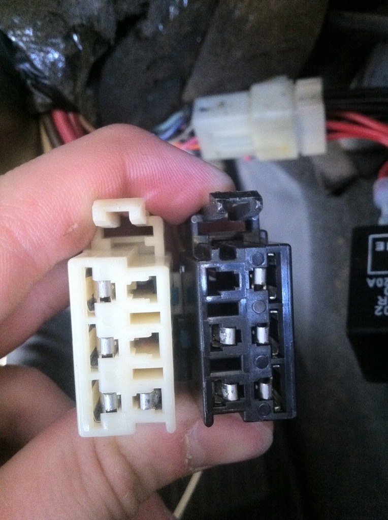
NOTE! The Electrical connectors with FEMALE PINS that pulg into the Ignition Switch can spread and male poor connection with the male pins inside the switch. Check the female pins inside the two power connectors:
Once you sand the burned marks off the bent female pins, rebend them back so that the tong makes better contact with the male pins inside the switch. There are TWO damaged large pins in the black plug and one on the white plug.
Bill
Update 24 May 13
I have to admit that; just because the ignition switch contacts look burnt, they still could be fine. The problem occurs when the contacts start building resistance from the carbon, poor contact continuity and burnt contacts.
That excessive resistance causes the 12 VDC battery voltage supplied to the switch and controlled by those contacts to be something LESS than full battery voltage. If the switch is marginally defective, it may work one ignition sequence and fail horribly the next. Please check the ignition switch resistance AND electrical output after cycling it several times.
Most of the problems with our ignition switches are, the contacts do not close perfectly parallel and after thousands of OPEN/SHUT cycles, the contact arms heat up and loose tension. That�s when the resistance starts building and the switch contacts generate excessive heat and degraded voltage outputs.
Before any ignition switch is rebuilt/repaired, you should measure the closed contacts with an OHM Meter and see what you have resistance wise. Measuring all the contacts requires cycling the switch thru all of its available positions. Write down the resistance value before repair and then again after repair.
When you repair/rebuild the switch, re-arch the movable contact arms so that they shut with more pressure.
One of the reasons that the contacts get hot is, some circuits draw a moderate amounts of current. If the contacts don�t close perfectly parallel, there is only a very small contact point for the current to flow thru. That causes heat and excessive arching when the contacts shut.
Im going to reassemble a switch and slide some wet and dry sand paper between the closed contacts and work the paper between the contacts to LAP the contacts so that they have a larger contact point
NOTE! Anytime you clean/sand or file any electrical contact, you should finish the surface as smooth as you can and before finial reassembly, clean the contacts with isopropyl alcohol so that there is no grease or grit between the contacts.
As always, CHECK THE RESISTANCE of each contact in the switch (you have to cycle it thru all it positions) and make sure that it is not excessive. When you re-arch the movable arms, if you are TOO AGGRESSIVE, the switch contacts will never open when the arm is pushed open and that will cause an ignition circuit to remain ON when its suppose to be OFF. That will cause excessive battery current draw in the sleep mode and KILL the battery in short order.
Something else that needs to be examined is the female pins in the ignition switch connector. If they are spread and make poor contact, they also can cause lower ignition switch output voltages. I have seen female pin contacts so loose that they heat up and melt the connector causing ignition switch failure on all outputs for that 12 VDC circuit.
Look at the picture provided. Two of the contacts in the black connector (the two on the inboard contacts) are spread apart and have signs of electrical arcing and carbon. They need to be cleaned and the tong needs to be bent so that it makes better contact with the male pin inside the switch
I will add this to my Ignition Switch post.
HERE IS THE 99 c5 SCHEMATIC OF THE IGNITION SWITCH OUTPUT :
UPDATE 11 / 15/ 2023 IGNITION SWITCH CONNECTOR FEMALE PIN INSPECTION.
Along with ignition switch inspection repair and replacement, An Inspection shoule also be conducted on the TWO Car Harness Connectors that connect to the ignition switch. Over time, HEAT & Cold Cycles along with vibration causes the FEMALE PINS in all of our connectors to spread apart and make a poor connection with the associated MALE PIN inside the Ignition Switch.
If you have an ignition switch issue or your modules or the CAR just randomly shuts off, POOR CONNECTIONS inside the ignition switch connectors could be an issue.
Its a VERY COMMON ISSUE!
CONNECTOR INSPECTION:
- Disconnect the Negative battery terminal.
- Disconnect the Two Main Connectors that connect to the Ignition Switch.
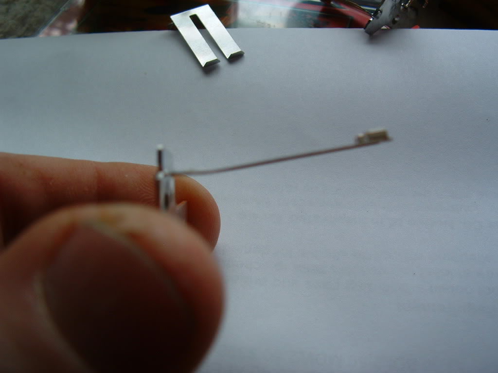
- Inspect the Female Pins & The plastic wells that the pins fit into. Look for discoloration, Melted Plastic and pin deformation. The only war to absolutely insure that the female pins are not spread apart far enough to make a poor intermittent connection is to do a PIN PUSH PULL TEST. You need to find a spare male pin that is the exact same thickness as the male pin inside the Ignition Switch Connector Well.
I have used a Fuse to construct a TEST pin. Snap the Fuse inhalf. Use a file and sand paper to trim and shape the Fuse Spade pin to the correct thickness and width as the male pin inside of the ignition switch
- Once you have a large and small test pin, you can use them to test each harness connector FEMALE pin for proper fit tension. Its called a PIN PUSH PULL TEST.
- Insert the Male Test Pin into the Harness Female pin. There should be a noticeable snug insertion resistance and removable resistance when the pin is inserted and removed. IF, the male pin is loose or NO resistance to insertion or removal, yiou either need to replace that/those pins OR you can remove that/those pins and tighten up the little TONG that makes electrical contact with the male pin. NOTE! Make a diagram or take a picture of the wiring placement inside the connector/s if you disassemble the connector!!
Bill
Bill
02-26-2008, 02:05 AM
#2
Tech Contributor
Thread Starter
Member Since: Dec 1999
Location: Anthony TX
Posts: 32,735
Received 2,180 Likes
on
1,583 Posts
CI 6,7,8,9,11 Vet
St. Jude Donor '08
Here are all the contacts cleaned up:
Attachment 48164984
I used a mechanical pencil with sand paper glued to the eraser to clean the fixed contacts. The eraser was trimmed down to fit the recess in the switch housing:
Attachment 48164985
Attachment 48164986
Once the contacts are cleaned up, bend the contact arms so that they apply more tension on the fixed contacts. It doesn't need too much bending:
Attachment 48164987
Once you apply more tension to the contacts, you will need to be careful when reinserting the arms back into the switch. The movable contact pads will tend to hang up on the fixed contacts. Assist them over the fixed contacts. I used a hooked paper clip to raise the arm over the fixed contact.
I used two flat blade screwdrivers to apply force to contacts A & B inside the switch contact well to keep the contact arms forced down on the fixed contacts to prevent them from popping out of place while installing the green cap. Once the contacts are in place,
Attachment 48164988
snap the green cap back on the switch. Check the CLEANED contacts with an ohm meter. They should read very close to ZERO OHMS.
Please feel free to ask me any questions that you have. I feel I'm a IGNITION SWITCH expert now!
Marks old NASTY broken switch is as good as new!!!!!!!!!!
* NOTE!!!!! UP_DATED 10 Sep 2012:
Some DO's and DONT's
1. It is NOT necessary to disassemble the lower portion of the switch!! There is NOTHING in there electrical related!
2. Electrical contact cleaning: Deeply pitted contacts can be cleaned using 400 Wet & Dry paper but should be polished with finer & finer grits to a highly polished surface 400, 600, 800 1000 grit wet & dry paper and cleaned with alcohol when done polishing. If there not deeply pitted start with 800 grit. It is strongly recommended to assemble the switch contact arms and place sand paper between the contacts. Apply force on the movable contact arm and pull the sand paper THRU the contacts. This will seat the upper and lower contacts and put a larger contact patch on the contacts. The larger the contact patch on the switch contacts allow the contacts to pass higher currents before over heating!
3. Measure the repaired contacts with an OHM METER before reassembly!! If you dont have ZERO ohms, figure out why and fix it! Make sure that the OHM Meter is on the ohms X1 Scale or in auto mode and your really are reading ONE OHM or less. Cycle the switch several times and make sure you get constant good resistance readings!
4. When you insert the key into the switch lock tumbler, the end of the key pushes on the small button on the center of the tumbler well. Its important that you test the operation of that switch as it tells the BCM when the key is in or out of the switch/tumbler.
5. On the front of the tumbler is a small sensor. Inside that sensor are two small silver coated contacts. Those contacts read the resistor pellet embeded in your key. Measure the pellet in your key. insert the key into the sensor and measure the output of the sensor with the key in it. The two readings should match. If they dont the sensor contacts are dirty or damaged.
BC
Heres the procedure for removing the ignition switch from the dash:
Ignition Switch Replacement
Removal Procedure
Caution
Before servicing any electrical component, the ignition key must be in the OFF or LOCK position and all electrical loads must be OFF, unless instructed otherwise in these procedures. If a tool or equipment could easily come in contact with a live exposed electrical terminal, also disconnect the negative battery cable. Failure to follow these precautions may cause personal injury and/or damage to the vehicle or its components.
Disconnect the negative battery cable.
Apply the parking brake.
Remove the console. Refer to Compartment Replacement - Instrument Panel (I/P) .
+++++++++++++++++++++++++++++++++
--------------------------------------------------------------------------------
Compartment Replacement - Instrument Panel (I/P)
Removal Procedure
Open the instrument panel (I/P) passenger compartment door.
Disconnect the electrical connector from the I/P compartment lamp switch.
Remove the trim plugs from the bottom of the compartment door. Reach behind the compartment door and push the plugs out. Use a suitable flat bladed tool on the front side to remove the plugs, if necessary.
Remove the lower retaining bolts from the I/P compartment.
Remove the side and upper retaining screws from the I/P compartment.
Slowly pull the I/P compartment just enough to disconnect the wiring harness connector from the inflatable restraint module switch.
Remove the I/P compartment.
Installation Procedure
Connect the wiring harness connector to the inflatable restraint I/P module switch connector.
Install the I/P compartment.
Loosely install the screw which retains the side of the I/P compartment, in order to align the nut on the passenger SIR bracket.
Notice
Use the correct fastener in the correct location. Replacement fasteners must be the correct part number for that application. Fasteners requiring replacement or fasteners requiring the use of thread locking compound or sealant are identified in the service procedure. Do not use paints, lubricants, or corrosion inhibitors on fasteners or fastener joint surfaces unless specified. These coatings affect fastener torque and joint clamping force and may damage the fastener. Use the correct tightening sequence and specifications when installing fasteners in order to avoid damage to parts and systems.
Install the upper retaining screw to the I/P compartment. Tighten
Tighten the retaining screw to 1.9 N�m (17 lb in).
Install the lower retaining bolts to the I/P compartment. Tighten
Tighten the retaining bolts to 12 N�m (106 lb in).
Align and hold the I/P compartment to the I/P, then install the side retaining screw to the I/P compartment. Tighten
Tighten the retaining screw to 1.9 N�m (17 lb in).
Install the trim plugs to the I/P compartment door.
Connect the electrical connector to the I/P compartment lamp switch.
Close the I/P passenger compartment door.
++++++++++++++++++++++++++++++++++
Remove the IP accessory trim plate. Refer to Trim Plate Replacement - Instrument Panel (I/P) Accessory .
++++++++++++++++++++++++++++++++++
Trim Plate Replacement - Instrument Panel (I/P) Accessory
Removal Procedure
Apply the parking brake for additional clearance around the parking brake lever.
Shift the transmission into SECOND (A/T), or FOURTH (M/T).
Remove the console. Refer to Console Replacement .
Grasp the shift control boot (M/T) and apply light pressure in toward the shift control lever, to begin to release the shift boot retaining tabs from the instrument panel (IP) accessory trim plate.
Using light pressure, continue to release the remaining boot retaining tabs, then lift the boot away from the trim plate.
Open the cigar lighter door and remove the ashtray.
Remove the IP accessory trim plate grille. Pry gently at the side edge with a flat-bladed screwdriver to release the tab.
Remove the accessory trim plate retaining screws next to the cigar lighter and behind the ashtray.
Remove the accessory trim plate retaining screw in the grille opening.
Grasp the sides of the accessory trim plate near the curve at the base.
Pull the trim plate rearward to release the locking tabs. Lift the rear of the trim plate to clear the driveline tunnel studs.
Disconnect the electrical connector from the cigar lighter.
Rotate the shift control boot (M/T) and reposition one end down into the shifter opening in the trim plate.
Lift the accessory trim plate over the shifter (and shift control boot, M/T), and remove the trim plate.
Installation Procedure
Lower the IP accessory trim plate over the shifter and under the parking brake lever. Position the shift control boot (M/T) as during removal and insert the boot up through the shifter opening in the accessory trim plate.
Connect the electrical connector to the cigar lighter.
Install the trim plate into position. Align the locator tabs and the locking tabs to the slots.
Begin to install the upper locator tabs and the upper locking tabs, then work downward to install the remaining tabs. Install the rear of the trim plate onto the driveline tunnel studs.
Notice
Use the correct fastener in the correct location. Replacement fasteners must be the correct part number for that application. Fasteners requiring replacement or fasteners requiring the use of thread locking compound or sealant are identified in the service procedure. Do not use paints, lubricants, or corrosion inhibitors on fasteners or fastener joint surfaces unless specified. These coatings affect fastener torque and joint clamping force and may damage the fastener. Use the correct tightening sequence and specifications when installing fasteners in order to avoid damage to parts and systems.
Install the accessory trim plate retaining screws. Tighten
Tighten the IP accessory trim plate retaining screw next to cigar lighter to 1.9 N�m (17 lb in).
Tighten the IP accessory trim plate retaining screw behind ashtray to 1.9 N�m (17 lb in).
Tighten the IP accessory trim plate retaining screw in grille opening to 1.9 N�m (17 lb in).
Install the accessory trim plate grille. Position the grille, then push to secure.
Install the ashtray.
Install the console. Refer to Console Replacement .
Align the shift control boot to the IP accessory trim plate opening, then press to lock the boot retaining tabs.
Adjust the shape of the boot for appearance, if necessary.
Shift the transmission into PARK (A/T), or REVERSE (M/T).
Release the parking brake.
++++++++++++++++++++++++++++++++++
Remove the driver knee bolster trim panel. Refer to Trim Panel Replacement - Knee Bolster .
+++++++++++++++++++++++++++++++++
Trim Panel Replacement - Knee Bolster
Removal Procedure
Remove the console. Refer to Console Replacement .
Remove the IP accessory trim plate. Refer to Trim Plate Replacement - Instrument Panel (I/P) Accessory .
Remove the fog lamp, rear compartment lid release switch.
Pry carefully at the lower edge of the switch to release the locking tab.
Disconnect the electrical connector from the switch.
Remove the driver knee bolster trim panel retaining screw behind the fog lamp, rear compartment lid release switch.
Remove the driver knee bolster trim panel lower retaining screws.
Grasp the trim panel at the side edges.
Pull firmly rearward to release the locking tabs.
Disconnect the electrical connector from the inside air temperature sensor, if equipped.
Remove the trim panel.
Installation Procedure
Connect the electrical connector to the inside air temperature sensor, if equipped.
Insert the electrical connector for the fog lamp, rear compartment lid release switch through the opening in the trim panel.
Install the driver knee bolster trim panel.
If equipped, insert the inside air temperature sensor wire down into the driver knee bolster bracket to avoid pinching the wire.
Align the locking tabs to the slots.
Push the trim panel to secure.
Loosely install the screws retaining the bottom of the driver knee bolster trim panel, in order to align the nuts on the knee bolster bracket.
Notice
Use the correct fastener in the correct location. Replacement fasteners must be the correct part number for that application. Fasteners requiring replacement or fasteners requiring the use of thread locking compound or sealant are identified in the service procedure. Do not use paints, lubricants, or corrosion inhibitors on fasteners or fastener joint surfaces unless specified. These coatings affect fastener torque and joint clamping force and may damage the fastener. Use the correct tightening sequence and specifications when installing fasteners in order to avoid damage to parts and systems.
Install the remaining driver knee bolster trim panel retaining screw. Tighten
Tighten the driver knee bolster trim panel retaining screw behind fog lamp, rear compartment lid release switch to 1.8 N�m (16 lb in).
Tighten the driver knee bolster trim panel lower retaining screws to 1.8 N�m (16 lb in).
Install the fog lamp, rear compartment lid release switch.
Connect the electrical connector to the switch.
Align the switch, then push to secure.
Install the IP accessory trim plate. Refer to Trim Plate Replacement - Instrument Panel (I/P) Accessory .
Install the console. Refer to Console Replacement .
+++++++++++++++++++++++++++++++++
Remove the ignition switch lock cylinder electrical connector from the retaining tab on the side of the ignition switch.
Disconnect the lock cylinder electrical connector.
Important
Take note of the way in which the ignition switch lock cylinder wire is wrapped around the base of the ignition switch bezel.
Remove the ignition switch bezel. Carefully pull to unsnap.
Remove the hazard warning switch wiring harness from the ignition switch retainer.
Disconnect the ignition switch electrical connectors.
Disconnect the park/lock cable (A/T) from the ignition switch.
Insert the key into the ignition switch, then turn the ignition to ON.
Using a flat bladed screwdriver or other suitable tool, depress the park/lock cable retaining tab (located on the underside of the switch near the base of the cable).
Pull to remove the cable.
Remove the ignition switch retaining bolts.
Remove the ignition switch.
Installation Procedure
Install the ignition switch into position on the ignition switch housing bracket.
Notice
Use the correct fastener in the correct location. Replacement fasteners must be the correct part number for that application. Fasteners requiring replacement or fasteners requiring the use of thread locking compound or sealant are identified in the service procedure. Do not use paints, lubricants, or corrosion inhibitors on fasteners or fastener joint surfaces unless specified. These coatings affect fastener torque and joint clamping force and may damage the fastener. Use the correct tightening sequence and specifications when installing fasteners in order to avoid damage to parts and systems.
Install the ignition switch retaining bolts. Tighten
Tighten the ignition switch retaining bolts to 5.5 N�m (49 lb in).
Install the park/lock cable (A/T) to the ignition switch (still in the ON position). Push to secure the cable retaining tab.
Connect the ignition switch electrical connections.
Install the hazard warning switch wiring harness to the ignition switch retainer.
Install the ignition switch bezel to the switch.
Wrap the ignition switch lock cylinder wire around the base of the ignition switch bezel, as noted during removal.
Align the bezel slots to the lock cylinder pins, then push to secure.
Connect the lock cylinder electrical connector.
Install the lock cylinder electrical connector to the retaining tab on the side of the ignition switch.
Install the driver knee bolster trim panel. Refer to Trim Panel Replacement - Knee Bolster .
Install the IP accessory trim plate. Refer to Trim Plate Replacement - Instrument Panel (I/P) Accessory .
Install the console. Refer to Compartment Replacement - Instrument Panel (I/P) .
Connect the negative battery cable. Tighten
Tighten the negative battery cable bolt to 15 N�m (11 lb ft).
Program the transmitters. Refer to Transmitter Programming/Synchronization in Keyless Entry.
Release the parking brake.
-----------------------------------------------------------------------------------------------------
If you "THINK" you have an ignition switch issue, you can use a volt meter and measure the output of the ignition switch.
There are TWO voltages that power the critical modules in our cars. One is "HOT AT ALL TIMES" and the other is "HOT in ACC and ON". When you turn the ignition switch to ON, you can read the fuses listed below and you should see exactly what the battery puts out. If the electrical contacts inside the switch are burnt, there will be resistance in the circuit and the voltage output of the switch will be lower or even zero.
On top of the fuses are two small holes that you can insert pin point meter leads into and read that fuse terminal. MAKE SURE to read both holes. If the fuse happens to be blown, only the battery side will have voltage on it.
Heres another troubleshooting tip: If you read across the fuse; If it good, you should read ZERO VOLTS! If its bad, you will read BATTERY VOLTAGE.
Heres the schematic for the START /Crank side of the switch:
Attachment 48164989
Heres the schematic for the IPC and the voltage that you see on the IPC Volt Meter:
Here are the fuses powered by the "HOT in ACC and ON". part of the switch:
Ok,,,here are the fuses that your going to check:
Under Hood Fuse Center
ENG ING1 FUSE# 19
INJR 2 FUSE# 18
THROTCONT FUSE# 17
INJR 1 FUSE# 22
PCM FUSE# 16
F/PMP FUSE# 13
Instrument Panel Fuse block
BTSI BU Fuse# 21
BCM 13 Fuse# 22
IPC Fuse# 19
Check the VOLTAGE on these fuses when the ignition is in the ON position. There should be battery voltage on these fuses.
Another ignition switch troubleshooting aid is; If the engine will run when you HOLD the ignition switch to the CRANK position but dies when you release the key, the switch could be at fault.
SOME UP DATED Switch repair info Sep 2011:
Some additional guidance on the ignition switch repair.
Remember to re-arch the movable switch contacts so that they have better contact with the fixed contact point. Once there re-arched, you will need to use a hook (I used a bent paper clip) to ASSIST the arms over the FIXED contacts when your sliding them back into place!
Once the switch movable contact arms are in place, insert a piece of 600 grit wet and dry paper between the closed contacts and with a small pair of needle nose pliers or a pair of tweezers (I use a small pair of curved hemostats),, Move the sand paper between the contacts while applying some pressure on top of the movable arm. Switch to 1000 grit and polish the contacts. Clean the contacts with alcohol.
What your doing is making the CONTACT AREA of that single switch larger than it was. That will give the contact more current carrying ability and better contact. Do that to each of the FIVE switches....
REMEMBER!! Measure the resistance of EACH of the newly cleaned, re-arched, sanded and polished and cleaned contacts to make sure you have very very close to ZERO ohms resistance when the contacts are shut! If you have resistance, go back and CLEAN the contacts with alcohol again
Here are a FEW UPDATES that have been added as we refine this repair process:
Recommned that you obtain some 600 grit wet and dry sand paper. Cut a strip about 6" long X 3/4" wide. Fold it in half so that you have sand paper on both sides. Work the sand paper in between all the contacts on one side of the switch. Pull and push the sand paper between the stationary contacts and movable contact arms. Doing this will lap in a bigger contact area between the two contacts thus allowing the switch to carry a bigger current load without heating up. When you are done lapping the contacts on one side, lap the other side.
NOTE! Make sure that you recheck the contact pressure on the contach arms to insure that they are still making firm contact. Clean the contacts and recheck the resistance of each switch.
NOTE! The Electrical connectors with FEMALE PINS that pulg into the Ignition Switch can spread and male poor connection with the male pins inside the switch. Check the female pins inside the two power connectors:
Attachment 48164990
Once you sand the burned marks off the bent female pins, rebend them back so that the tong makes better contact with the male pins inside the switch. There are TWO damaged large pins in the black plug and one on the white plug.
Bill
Update 24 May 13
I have to admit that; just because the ignition switch contacts look burnt, they still could be fine. The problem occurs when the contacts start building resistance from the carbon, poor contact continuity and burnt contacts.
That excessive resistance causes the 12 VDC battery voltage supplied to the switch and controlled by those contacts to be something LESS than full battery voltage. If the switch is marginally defective, it may work one ignition sequence and fail horribly the next. Please check the ignition switch resistance AND electrical output after cycling it several times.
Most of the problems with our ignition switches are, the contacts do not close perfectly parallel and after thousands of OPEN/SHUT cycles, the contact arms heat up and loose tension. That�s when the resistance starts building and the switch contacts generate excessive heat and degraded voltage outputs.
Before any ignition switch is rebuilt/repaired, you should measure the closed contacts with an OHM Meter and see what you have resistance wise. Measuring all the contacts requires cycling the switch thru all of its available positions. Write down the resistance value before repair and then again after repair.
When you repair/rebuild the switch, re-arch the movable contact arms so that they shut with more pressure.
One of the reasons that the contacts get hot is, some circuits draw a moderate amounts of current. If the contacts don�t close perfectly parallel, there is only a very small contact point for the current to flow thru. That causes heat and excessive arching when the contacts shut.
Im going to reassemble a switch and slide some wet and dry sand paper between the closed contacts and work the paper between the contacts to LAP the contacts so that they have a larger contact point
NOTE! Anytime you clean/sand or file any electrical contact, you should finish the surface as smooth as you can and before finial reassembly, clean the contacts with isopropyl alcohol so that there is no grease or grit between the contacts.
As always, CHECK THE RESISTANCE of each contact in the switch (you have to cycle it thru all it positions) and make sure that it is not excessive. When you re-arch the movable arms, if you are TOO AGGRESSIVE, the switch contacts will never open when the arm is pushed open and that will cause an ignition circuit to remain ON when its suppose to be OFF. That will cause excessive battery current draw in the sleep mode and KILL the battery in short order.
Something else that needs to be examined is the female pins in the ignition switch connector. If they are spread and make poor contact, they also can cause lower ignition switch output voltages. I have seen female pin contacts so loose that they heat up and melt the connector causing ignition switch failure on all outputs for that 12 VDC circuit.
Look at the picture provided. Two of the contacts in the black connector (the two on the inboard contacts) are spread apart and have signs of electrical arcing and carbon. They need to be cleaned and the tong needs to be bent so that it makes better contact with the male pin inside the switch
I will add this to my Ignition Switch post.
Attachment 48164990
HERE IS THE 99 c5 SCHEMATIC OF THE IGNITION SWITCH OUTPUT :
Attachment 48164992
UPDATE 11 / 15/ 2023 IGNITION SWITCH CONNECTOR FEMALE PIN INSPECTION.
Along with ignition switch inspection repair and replacement, An Inspection shoule also be conducted on the TWO Car Harness Connectors that connect to the ignition switch. Over time, HEAT & Cold Cycles along with vibration causes the FEMALE PINS in all of our connectors to spread apart and make a poor connection with the associated MALE PIN inside the Ignition Switch.
If you have an ignition switch issue or your modules or the CAR just randomly shuts off, POOR CONNECTIONS inside the ignition switch connectors could be an issue.
Its a VERY COMMON ISSUE!
CONNECTOR INSPECTION:
- Disconnect the Negative battery terminal.
- Disconnect the Two Main Connectors that connect to the Ignition Switch.
- Inspect the Female Pins & The plastic wells that the pins fit into. Look for discoloration, Melted Plastic and pin deformation. The only war to absolutely insure that the female pins are not spread apart far enough to make a poor intermittent connection is to do a PIN PUSH PULL TEST. You need to find a spare male pin that is the exact same thickness as the male pin inside the Ignition Switch Connector Well.
I have used a Fuse to construct a TEST pin. Snap the Fuse inhalf. Use a file and sand paper to trim and shape the Fuse Spade pin to the correct thickness and width as the male pin inside of the ignition switch
- Once you have a large and small test pin, you can use them to test each harness connector FEMALE pin for proper fit tension. Its called a PIN PUSH PULL TEST.
- Insert the Male Test Pin into the Harness Female pin. There should be a noticeable snug insertion resistance and removable resistance when the pin is inserted and removed. IF, the male pin is loose or NO resistance to insertion or removal, yiou either need to replace that/those pins OR you can remove that/those pins and tighten up the little TONG that makes electrical contact with the male pin. NOTE! Make a diagram or take a picture of the wiring placement inside the connector/s if you disassemble the connector!!
Bill
Bill
Attachment 48164984
I used a mechanical pencil with sand paper glued to the eraser to clean the fixed contacts. The eraser was trimmed down to fit the recess in the switch housing:
Attachment 48164985
Attachment 48164986
Once the contacts are cleaned up, bend the contact arms so that they apply more tension on the fixed contacts. It doesn't need too much bending:
Attachment 48164987
Once you apply more tension to the contacts, you will need to be careful when reinserting the arms back into the switch. The movable contact pads will tend to hang up on the fixed contacts. Assist them over the fixed contacts. I used a hooked paper clip to raise the arm over the fixed contact.
I used two flat blade screwdrivers to apply force to contacts A & B inside the switch contact well to keep the contact arms forced down on the fixed contacts to prevent them from popping out of place while installing the green cap. Once the contacts are in place,
Attachment 48164988
snap the green cap back on the switch. Check the CLEANED contacts with an ohm meter. They should read very close to ZERO OHMS.
Please feel free to ask me any questions that you have. I feel I'm a IGNITION SWITCH expert now!
Marks old NASTY broken switch is as good as new!!!!!!!!!!
* NOTE!!!!! UP_DATED 10 Sep 2012:
Some DO's and DONT's
1. It is NOT necessary to disassemble the lower portion of the switch!! There is NOTHING in there electrical related!
2. Electrical contact cleaning: Deeply pitted contacts can be cleaned using 400 Wet & Dry paper but should be polished with finer & finer grits to a highly polished surface 400, 600, 800 1000 grit wet & dry paper and cleaned with alcohol when done polishing. If there not deeply pitted start with 800 grit. It is strongly recommended to assemble the switch contact arms and place sand paper between the contacts. Apply force on the movable contact arm and pull the sand paper THRU the contacts. This will seat the upper and lower contacts and put a larger contact patch on the contacts. The larger the contact patch on the switch contacts allow the contacts to pass higher currents before over heating!
3. Measure the repaired contacts with an OHM METER before reassembly!! If you dont have ZERO ohms, figure out why and fix it! Make sure that the OHM Meter is on the ohms X1 Scale or in auto mode and your really are reading ONE OHM or less. Cycle the switch several times and make sure you get constant good resistance readings!
4. When you insert the key into the switch lock tumbler, the end of the key pushes on the small button on the center of the tumbler well. Its important that you test the operation of that switch as it tells the BCM when the key is in or out of the switch/tumbler.
5. On the front of the tumbler is a small sensor. Inside that sensor are two small silver coated contacts. Those contacts read the resistor pellet embeded in your key. Measure the pellet in your key. insert the key into the sensor and measure the output of the sensor with the key in it. The two readings should match. If they dont the sensor contacts are dirty or damaged.
BC
Heres the procedure for removing the ignition switch from the dash:
Ignition Switch Replacement
Removal Procedure
Caution
Before servicing any electrical component, the ignition key must be in the OFF or LOCK position and all electrical loads must be OFF, unless instructed otherwise in these procedures. If a tool or equipment could easily come in contact with a live exposed electrical terminal, also disconnect the negative battery cable. Failure to follow these precautions may cause personal injury and/or damage to the vehicle or its components.
Disconnect the negative battery cable.
Apply the parking brake.
Remove the console. Refer to Compartment Replacement - Instrument Panel (I/P) .
+++++++++++++++++++++++++++++++++
--------------------------------------------------------------------------------
Compartment Replacement - Instrument Panel (I/P)
Removal Procedure
Open the instrument panel (I/P) passenger compartment door.
Disconnect the electrical connector from the I/P compartment lamp switch.
Remove the trim plugs from the bottom of the compartment door. Reach behind the compartment door and push the plugs out. Use a suitable flat bladed tool on the front side to remove the plugs, if necessary.
Remove the lower retaining bolts from the I/P compartment.
Remove the side and upper retaining screws from the I/P compartment.
Slowly pull the I/P compartment just enough to disconnect the wiring harness connector from the inflatable restraint module switch.
Remove the I/P compartment.
Installation Procedure
Connect the wiring harness connector to the inflatable restraint I/P module switch connector.
Install the I/P compartment.
Loosely install the screw which retains the side of the I/P compartment, in order to align the nut on the passenger SIR bracket.
Notice
Use the correct fastener in the correct location. Replacement fasteners must be the correct part number for that application. Fasteners requiring replacement or fasteners requiring the use of thread locking compound or sealant are identified in the service procedure. Do not use paints, lubricants, or corrosion inhibitors on fasteners or fastener joint surfaces unless specified. These coatings affect fastener torque and joint clamping force and may damage the fastener. Use the correct tightening sequence and specifications when installing fasteners in order to avoid damage to parts and systems.
Install the upper retaining screw to the I/P compartment. Tighten
Tighten the retaining screw to 1.9 N�m (17 lb in).
Install the lower retaining bolts to the I/P compartment. Tighten
Tighten the retaining bolts to 12 N�m (106 lb in).
Align and hold the I/P compartment to the I/P, then install the side retaining screw to the I/P compartment. Tighten
Tighten the retaining screw to 1.9 N�m (17 lb in).
Install the trim plugs to the I/P compartment door.
Connect the electrical connector to the I/P compartment lamp switch.
Close the I/P passenger compartment door.
++++++++++++++++++++++++++++++++++
Remove the IP accessory trim plate. Refer to Trim Plate Replacement - Instrument Panel (I/P) Accessory .
++++++++++++++++++++++++++++++++++
Trim Plate Replacement - Instrument Panel (I/P) Accessory
Removal Procedure
Apply the parking brake for additional clearance around the parking brake lever.
Shift the transmission into SECOND (A/T), or FOURTH (M/T).
Remove the console. Refer to Console Replacement .
Grasp the shift control boot (M/T) and apply light pressure in toward the shift control lever, to begin to release the shift boot retaining tabs from the instrument panel (IP) accessory trim plate.
Using light pressure, continue to release the remaining boot retaining tabs, then lift the boot away from the trim plate.
Open the cigar lighter door and remove the ashtray.
Remove the IP accessory trim plate grille. Pry gently at the side edge with a flat-bladed screwdriver to release the tab.
Remove the accessory trim plate retaining screws next to the cigar lighter and behind the ashtray.
Remove the accessory trim plate retaining screw in the grille opening.
Grasp the sides of the accessory trim plate near the curve at the base.
Pull the trim plate rearward to release the locking tabs. Lift the rear of the trim plate to clear the driveline tunnel studs.
Disconnect the electrical connector from the cigar lighter.
Rotate the shift control boot (M/T) and reposition one end down into the shifter opening in the trim plate.
Lift the accessory trim plate over the shifter (and shift control boot, M/T), and remove the trim plate.
Installation Procedure
Lower the IP accessory trim plate over the shifter and under the parking brake lever. Position the shift control boot (M/T) as during removal and insert the boot up through the shifter opening in the accessory trim plate.
Connect the electrical connector to the cigar lighter.
Install the trim plate into position. Align the locator tabs and the locking tabs to the slots.
Begin to install the upper locator tabs and the upper locking tabs, then work downward to install the remaining tabs. Install the rear of the trim plate onto the driveline tunnel studs.
Notice
Use the correct fastener in the correct location. Replacement fasteners must be the correct part number for that application. Fasteners requiring replacement or fasteners requiring the use of thread locking compound or sealant are identified in the service procedure. Do not use paints, lubricants, or corrosion inhibitors on fasteners or fastener joint surfaces unless specified. These coatings affect fastener torque and joint clamping force and may damage the fastener. Use the correct tightening sequence and specifications when installing fasteners in order to avoid damage to parts and systems.
Install the accessory trim plate retaining screws. Tighten
Tighten the IP accessory trim plate retaining screw next to cigar lighter to 1.9 N�m (17 lb in).
Tighten the IP accessory trim plate retaining screw behind ashtray to 1.9 N�m (17 lb in).
Tighten the IP accessory trim plate retaining screw in grille opening to 1.9 N�m (17 lb in).
Install the accessory trim plate grille. Position the grille, then push to secure.
Install the ashtray.
Install the console. Refer to Console Replacement .
Align the shift control boot to the IP accessory trim plate opening, then press to lock the boot retaining tabs.
Adjust the shape of the boot for appearance, if necessary.
Shift the transmission into PARK (A/T), or REVERSE (M/T).
Release the parking brake.
++++++++++++++++++++++++++++++++++
Remove the driver knee bolster trim panel. Refer to Trim Panel Replacement - Knee Bolster .
+++++++++++++++++++++++++++++++++
Trim Panel Replacement - Knee Bolster
Removal Procedure
Remove the console. Refer to Console Replacement .
Remove the IP accessory trim plate. Refer to Trim Plate Replacement - Instrument Panel (I/P) Accessory .
Remove the fog lamp, rear compartment lid release switch.
Pry carefully at the lower edge of the switch to release the locking tab.
Disconnect the electrical connector from the switch.
Remove the driver knee bolster trim panel retaining screw behind the fog lamp, rear compartment lid release switch.
Remove the driver knee bolster trim panel lower retaining screws.
Grasp the trim panel at the side edges.
Pull firmly rearward to release the locking tabs.
Disconnect the electrical connector from the inside air temperature sensor, if equipped.
Remove the trim panel.
Installation Procedure
Connect the electrical connector to the inside air temperature sensor, if equipped.
Insert the electrical connector for the fog lamp, rear compartment lid release switch through the opening in the trim panel.
Install the driver knee bolster trim panel.
If equipped, insert the inside air temperature sensor wire down into the driver knee bolster bracket to avoid pinching the wire.
Align the locking tabs to the slots.
Push the trim panel to secure.
Loosely install the screws retaining the bottom of the driver knee bolster trim panel, in order to align the nuts on the knee bolster bracket.
Notice
Use the correct fastener in the correct location. Replacement fasteners must be the correct part number for that application. Fasteners requiring replacement or fasteners requiring the use of thread locking compound or sealant are identified in the service procedure. Do not use paints, lubricants, or corrosion inhibitors on fasteners or fastener joint surfaces unless specified. These coatings affect fastener torque and joint clamping force and may damage the fastener. Use the correct tightening sequence and specifications when installing fasteners in order to avoid damage to parts and systems.
Install the remaining driver knee bolster trim panel retaining screw. Tighten
Tighten the driver knee bolster trim panel retaining screw behind fog lamp, rear compartment lid release switch to 1.8 N�m (16 lb in).
Tighten the driver knee bolster trim panel lower retaining screws to 1.8 N�m (16 lb in).
Install the fog lamp, rear compartment lid release switch.
Connect the electrical connector to the switch.
Align the switch, then push to secure.
Install the IP accessory trim plate. Refer to Trim Plate Replacement - Instrument Panel (I/P) Accessory .
Install the console. Refer to Console Replacement .
+++++++++++++++++++++++++++++++++
Remove the ignition switch lock cylinder electrical connector from the retaining tab on the side of the ignition switch.
Disconnect the lock cylinder electrical connector.
Important
Take note of the way in which the ignition switch lock cylinder wire is wrapped around the base of the ignition switch bezel.
Remove the ignition switch bezel. Carefully pull to unsnap.
Remove the hazard warning switch wiring harness from the ignition switch retainer.
Disconnect the ignition switch electrical connectors.
Disconnect the park/lock cable (A/T) from the ignition switch.
Insert the key into the ignition switch, then turn the ignition to ON.
Using a flat bladed screwdriver or other suitable tool, depress the park/lock cable retaining tab (located on the underside of the switch near the base of the cable).
Pull to remove the cable.
Remove the ignition switch retaining bolts.
Remove the ignition switch.
Installation Procedure
Install the ignition switch into position on the ignition switch housing bracket.
Notice
Use the correct fastener in the correct location. Replacement fasteners must be the correct part number for that application. Fasteners requiring replacement or fasteners requiring the use of thread locking compound or sealant are identified in the service procedure. Do not use paints, lubricants, or corrosion inhibitors on fasteners or fastener joint surfaces unless specified. These coatings affect fastener torque and joint clamping force and may damage the fastener. Use the correct tightening sequence and specifications when installing fasteners in order to avoid damage to parts and systems.
Install the ignition switch retaining bolts. Tighten
Tighten the ignition switch retaining bolts to 5.5 N�m (49 lb in).
Install the park/lock cable (A/T) to the ignition switch (still in the ON position). Push to secure the cable retaining tab.
Connect the ignition switch electrical connections.
Install the hazard warning switch wiring harness to the ignition switch retainer.
Install the ignition switch bezel to the switch.
Wrap the ignition switch lock cylinder wire around the base of the ignition switch bezel, as noted during removal.
Align the bezel slots to the lock cylinder pins, then push to secure.
Connect the lock cylinder electrical connector.
Install the lock cylinder electrical connector to the retaining tab on the side of the ignition switch.
Install the driver knee bolster trim panel. Refer to Trim Panel Replacement - Knee Bolster .
Install the IP accessory trim plate. Refer to Trim Plate Replacement - Instrument Panel (I/P) Accessory .
Install the console. Refer to Compartment Replacement - Instrument Panel (I/P) .
Connect the negative battery cable. Tighten
Tighten the negative battery cable bolt to 15 N�m (11 lb ft).
Program the transmitters. Refer to Transmitter Programming/Synchronization in Keyless Entry.
Release the parking brake.
-----------------------------------------------------------------------------------------------------
If you "THINK" you have an ignition switch issue, you can use a volt meter and measure the output of the ignition switch.
There are TWO voltages that power the critical modules in our cars. One is "HOT AT ALL TIMES" and the other is "HOT in ACC and ON". When you turn the ignition switch to ON, you can read the fuses listed below and you should see exactly what the battery puts out. If the electrical contacts inside the switch are burnt, there will be resistance in the circuit and the voltage output of the switch will be lower or even zero.
On top of the fuses are two small holes that you can insert pin point meter leads into and read that fuse terminal. MAKE SURE to read both holes. If the fuse happens to be blown, only the battery side will have voltage on it.
Heres another troubleshooting tip: If you read across the fuse; If it good, you should read ZERO VOLTS!
If its bad, you will read BATTERY VOLTAGE.Heres the schematic for the START /Crank side of the switch:
Attachment 48164989
Heres the schematic for the IPC and the voltage that you see on the IPC Volt Meter:
Here are the fuses powered by the "HOT in ACC and ON". part of the switch:
Ok,,,here are the fuses that your going to check:
Under Hood Fuse Center
ENG ING1 FUSE# 19
INJR 2 FUSE# 18
THROTCONT FUSE# 17
INJR 1 FUSE# 22
PCM FUSE# 16
F/PMP FUSE# 13
Instrument Panel Fuse block
BTSI BU Fuse# 21
BCM 13 Fuse# 22
IPC Fuse# 19
Check the VOLTAGE on these fuses when the ignition is in the ON position. There should be battery voltage on these fuses.
Another ignition switch troubleshooting aid is; If the engine will run when you HOLD the ignition switch to the CRANK position but dies when you release the key, the switch could be at fault.
SOME UP DATED Switch repair info Sep 2011:
Some additional guidance on the ignition switch repair.
Remember to re-arch the movable switch contacts so that they have better contact with the fixed contact point. Once there re-arched, you will need to use a hook (I used a bent paper clip) to ASSIST the arms over the FIXED contacts when your sliding them back into place!
Once the switch movable contact arms are in place, insert a piece of 600 grit wet and dry paper between the closed contacts and with a small pair of needle nose pliers or a pair of tweezers (I use a small pair of curved hemostats),, Move the sand paper between the contacts while applying some pressure on top of the movable arm. Switch to 1000 grit and polish the contacts. Clean the contacts with alcohol.
What your doing is making the CONTACT AREA of that single switch larger than it was. That will give the contact more current carrying ability and better contact. Do that to each of the FIVE switches....
REMEMBER!! Measure the resistance of EACH of the newly cleaned, re-arched, sanded and polished and cleaned contacts to make sure you have very very close to ZERO ohms resistance when the contacts are shut! If you have resistance, go back and CLEAN the contacts with alcohol again
Here are a FEW UPDATES that have been added as we refine this repair process:
Recommned that you obtain some 600 grit wet and dry sand paper. Cut a strip about 6" long X 3/4" wide. Fold it in half so that you have sand paper on both sides. Work the sand paper in between all the contacts on one side of the switch. Pull and push the sand paper between the stationary contacts and movable contact arms. Doing this will lap in a bigger contact area between the two contacts thus allowing the switch to carry a bigger current load without heating up. When you are done lapping the contacts on one side, lap the other side.
NOTE! Make sure that you recheck the contact pressure on the contach arms to insure that they are still making firm contact. Clean the contacts and recheck the resistance of each switch.
NOTE! The Electrical connectors with FEMALE PINS that pulg into the Ignition Switch can spread and male poor connection with the male pins inside the switch. Check the female pins inside the two power connectors:
Attachment 48164990
Once you sand the burned marks off the bent female pins, rebend them back so that the tong makes better contact with the male pins inside the switch. There are TWO damaged large pins in the black plug and one on the white plug.
Bill
Update 24 May 13
I have to admit that; just because the ignition switch contacts look burnt, they still could be fine. The problem occurs when the contacts start building resistance from the carbon, poor contact continuity and burnt contacts.
That excessive resistance causes the 12 VDC battery voltage supplied to the switch and controlled by those contacts to be something LESS than full battery voltage. If the switch is marginally defective, it may work one ignition sequence and fail horribly the next. Please check the ignition switch resistance AND electrical output after cycling it several times.
Most of the problems with our ignition switches are, the contacts do not close perfectly parallel and after thousands of OPEN/SHUT cycles, the contact arms heat up and loose tension. That�s when the resistance starts building and the switch contacts generate excessive heat and degraded voltage outputs.
Before any ignition switch is rebuilt/repaired, you should measure the closed contacts with an OHM Meter and see what you have resistance wise. Measuring all the contacts requires cycling the switch thru all of its available positions. Write down the resistance value before repair and then again after repair.
When you repair/rebuild the switch, re-arch the movable contact arms so that they shut with more pressure.
One of the reasons that the contacts get hot is, some circuits draw a moderate amounts of current. If the contacts don�t close perfectly parallel, there is only a very small contact point for the current to flow thru. That causes heat and excessive arching when the contacts shut.
Im going to reassemble a switch and slide some wet and dry sand paper between the closed contacts and work the paper between the contacts to LAP the contacts so that they have a larger contact point
NOTE! Anytime you clean/sand or file any electrical contact, you should finish the surface as smooth as you can and before finial reassembly, clean the contacts with isopropyl alcohol so that there is no grease or grit between the contacts.
As always, CHECK THE RESISTANCE of each contact in the switch (you have to cycle it thru all it positions) and make sure that it is not excessive. When you re-arch the movable arms, if you are TOO AGGRESSIVE, the switch contacts will never open when the arm is pushed open and that will cause an ignition circuit to remain ON when its suppose to be OFF. That will cause excessive battery current draw in the sleep mode and KILL the battery in short order.
Something else that needs to be examined is the female pins in the ignition switch connector. If they are spread and make poor contact, they also can cause lower ignition switch output voltages. I have seen female pin contacts so loose that they heat up and melt the connector causing ignition switch failure on all outputs for that 12 VDC circuit.
Look at the picture provided. Two of the contacts in the black connector (the two on the inboard contacts) are spread apart and have signs of electrical arcing and carbon. They need to be cleaned and the tong needs to be bent so that it makes better contact with the male pin inside the switch
I will add this to my Ignition Switch post.
Attachment 48164990
HERE IS THE 99 c5 SCHEMATIC OF THE IGNITION SWITCH OUTPUT :
Attachment 48164992
UPDATE 11 / 15/ 2023 IGNITION SWITCH CONNECTOR FEMALE PIN INSPECTION.
Along with ignition switch inspection repair and replacement, An Inspection shoule also be conducted on the TWO Car Harness Connectors that connect to the ignition switch. Over time, HEAT & Cold Cycles along with vibration causes the FEMALE PINS in all of our connectors to spread apart and make a poor connection with the associated MALE PIN inside the Ignition Switch.
If you have an ignition switch issue or your modules or the CAR just randomly shuts off, POOR CONNECTIONS inside the ignition switch connectors could be an issue.
Its a VERY COMMON ISSUE!
CONNECTOR INSPECTION:
- Disconnect the Negative battery terminal.
- Disconnect the Two Main Connectors that connect to the Ignition Switch.
- Inspect the Female Pins & The plastic wells that the pins fit into. Look for discoloration, Melted Plastic and pin deformation. The only war to absolutely insure that the female pins are not spread apart far enough to make a poor intermittent connection is to do a PIN PUSH PULL TEST. You need to find a spare male pin that is the exact same thickness as the male pin inside the Ignition Switch Connector Well.
I have used a Fuse to construct a TEST pin. Snap the Fuse inhalf. Use a file and sand paper to trim and shape the Fuse Spade pin to the correct thickness and width as the male pin inside of the ignition switch
- Once you have a large and small test pin, you can use them to test each harness connector FEMALE pin for proper fit tension. Its called a PIN PUSH PULL TEST.
- Insert the Male Test Pin into the Harness Female pin. There should be a noticeable snug insertion resistance and removable resistance when the pin is inserted and removed. IF, the male pin is loose or NO resistance to insertion or removal, yiou either need to replace that/those pins OR you can remove that/those pins and tighten up the little TONG that makes electrical contact with the male pin. NOTE! Make a diagram or take a picture of the wiring placement inside the connector/s if you disassemble the connector!!
Bill
Bill
Last edited by Bill Curlee; 11-15-2023 at 11:41 PM. Reason: added ignition switch repair instructions 18 Mar 13
The following 16 users liked this post by Bill Curlee:
Beer:30 (04-16-2019),
CaPilotMark (11-05-2017),
CorvetteBrent (09-12-2018),
Evilbeard (08-05-2019),
flyingmonkey1 (03-31-2016),
and 11 others liked this post.
 02-26-2008, 08:04 AM
#4
Le Mans Master

Member Since: Sep 2003
Location: Farmington CT
Posts: 6,126
Received 160 Likes
on
125 Posts
Cruise-In VII Veteran
Bill this is awesome!!!
Both of my high mileage C5's have been a somewhat finicky when starting ever so often, now I know why
Ayeroff had this problem on his 2k vert a few month ago
Both of my high mileage C5's have been a somewhat finicky when starting ever so often, now I know why
Ayeroff had this problem on his 2k vert a few month ago
02-26-2008, 08:36 AM
#5
Team Owner

Member Since: Mar 2007
Location: Right Corner Pocket of Illinois
Posts: 32,251
Received 1,491 Likes
on
1,005 Posts
No-IL Events Coordinator
2020 C6 of the Year Finalist - Unmodified
2020 Corvette of the Year Finalist (appearance mods)
C6 of Year Winner (appearance mods) 2019
2018 C6 of Year Finalist
St. Jude Donor '12-'13-'14-'15-'16-'17-'18-'19-'20-'21-'22-'23-'24


Thanks for a great DYI write-up! I wonder what the dealership would charge for "new parts" and install? 

 02-26-2008, 10:25 AM
#7
Advanced

Member Since: Aug 2006
Location: Bellingham Washington
Posts: 88
Likes: 0
Received 2 Likes
on
1 Post
Wow Bill, This thread is AWESOME 
I'm so happy I dropped the old switch in the mail to you!! Now I know what went wrong and many others can benefit from this!!
You ROCK!!
I'm so happy I dropped the old switch in the mail to you!! Now I know what went wrong and many others can benefit from this!!
You ROCK!!
The following 2 users liked this post by fastvetZ06:
CorvetteBrent (09-12-2018),
Dave70 (04-19-2016)
02-26-2008, 12:53 PM
#9
Tech Contributor
Thread Starter
Member Since: Dec 1999
Location: Anthony TX
Posts: 32,735
Received 2,180 Likes
on
1,583 Posts
CI 6,7,8,9,11 Vet
St. Jude Donor '08
Once I bent the movable contacts to add more contact pressure the switch has a more pronounced feel and the resistance readings were very good.
With the additional contact pressure there should be less contact arcing and deformation from heating. Hell,,, ,, for the price of that switch and the 30 min it took to fix it, it was WELL WORTH the effort. It will also allow you to troubleshoot and see if that switch was the ROOT cause of the problem. I love free repairs!
If this helps ONE person it was well worth the effort.
The next thing that I want to do is make a detailed list of the what each contact in the switch goes to and what symptoms/ faults are seen when that contact fails!
BC
With the additional contact pressure there should be less contact arcing and deformation from heating. Hell,,,
,, for the price of that switch and the 30 min it took to fix it, it was WELL WORTH the effort. It will also allow you to troubleshoot and see if that switch was the ROOT cause of the problem. I love free repairs! If this helps ONE person it was well worth the effort.
The next thing that I want to do is make a detailed list of the what each contact in the switch goes to and what symptoms/ faults are seen when that contact fails!
BC
The following 4 users liked this post by Bill Curlee:
CorvetteBrent (09-12-2018),
jlonardo1962 (06-14-2021),
Silver85 (10-01-2021),
vetintheblood (11-20-2020)
02-27-2008, 09:12 PM
#10
Tech Contributor
Thread Starter
Member Since: Dec 1999
Location: Anthony TX
Posts: 32,735
Received 2,180 Likes
on
1,583 Posts
CI 6,7,8,9,11 Vet
St. Jude Donor '08
TTT for those that have not seen the post.
BC
BC
02-28-2008, 10:19 AM
#11
Safety Car

Fantastic write up Bill! I saved this one to a file. Thank you!
 02-28-2008, 10:31 AM
#12
Instructor
Ha Bill,
Excellent analysis and documentation!
Did you also get the lock cylinder? If so what does it look like?
I'm thinking that's the part that seems bad on my spring back past the "On" position??
What do you think?
Excellent analysis and documentation!
Did you also get the lock cylinder? If so what does it look like?
I'm thinking that's the part that seems bad on my spring back past the "On" position??
What do you think?
02-28-2008, 01:08 PM
#13
Tech Contributor
Thread Starter
Member Since: Dec 1999
Location: Anthony TX
Posts: 32,735
Received 2,180 Likes
on
1,583 Posts
CI 6,7,8,9,11 Vet
St. Jude Donor '08
Nope! I just got the electrical portion of the switch. Once I tightened up the contact arms, the switch has a very nice precise feel.
The ON to crank and crank back to ON action is spring loaded and mine returns right back to the ON position. That spring is located in the section of the switch below where I was working. It too is able to be separated but I did not separate it. It seemed to be working fine
I do not believe that the lock cylinder has any positioning springs in it.
I have Never had one of those apart yet.
02-28-2008, 01:19 PM
#14
Le Mans Master

 03-05-2008, 01:35 PM
#18
Race Director

Great post! May explain my intermittent starting problem. I remove the key, jiggle the wheel a little, release and redepress the clutch, and that usually cures the ill. Faulty contacts on the ignition switch makes sense.


