
Alternator not Charging Battery
 02-16-2008, 09:35 AM
#1
Instructor

Thread Starter
Member Since: Jul 2003
Location: Salisbury NC
Posts: 107
Likes: 0
Received 0 Likes
on
0 Posts
Installed a serpentine kit on my 71 recently. I have had a chronic issue of my alternator not charging my battery back up. The kit came with an aftermarket alternator, one with an SFLP connector. I have tried all combinations of connecting the wires from the connector to the old 2 wire connection on the original harness, but no luck. The voltage gauge in the car shows straight up and down, indicating no charge or drain on the battery while the engine is running, except for when my SPAL fans come on, then the gauge shows a drain until they shut off, then it goes back to neutral current. I am willing to re run new wires from the alternator, but need to know where to run them to. I know the alternator is good, i had it checked out recently. Is there something that tells the alternator to start putting out a current back to the battery, or is it always supposed to put a positive charge back to the battery? If there is any area in which i am lacking, it is electrical, does anyone have any suggestions as to how i can wire my alternator so that it will start charging the battery back up?
 02-16-2008, 09:58 AM
#2
Safety Car


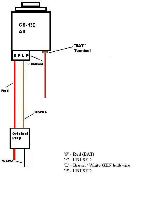
S - Red (Bat) If you use the red wire from the SI plug just tap it into the "S" location and run it to the "BAT" terminal along with the original "BAT" red wire.
F - Unused
L - Brown/White Gen bulb wire
P - Unused
I'm sure you have it wired correctly. Just learned this from the forum when I was going to use a serp system.
Hope it helps
F - Unused
L - Brown/White Gen bulb wire
P - Unused
I'm sure you have it wired correctly. Just learned this from the forum when I was going to use a serp system.
Hope it helps
02-16-2008, 10:35 AM
#3
Team Owner

Your description of the ammeter 'action' sounds like the alternator is working just fine. You would expect that the needle would be at zero if the charging system has stabilized. Does your battery go dead?
02-16-2008, 10:42 AM
#4
Team Owner
Member Since: Aug 2006
Location: Columbia Missouri
Posts: 24,125
Likes: 0
Received 9 Likes
on
9 Posts
 You have an Ammeter, not a volt meter. When things are normal it's supposed to be close to straight up and down until there is a substantial load.
Here is a wiring diagram for the CS alternator plug. The brown wire may also be white in some cars, and if you don't have a GEN light in your car you can use any switched 12V source so long as it has a resistor or a light bulb inline before the alternator.
 02-16-2008, 10:43 AM
#5
Instructor
Thread Starter
Member Since: Jul 2003
Location: Salisbury NC
Posts: 107
Likes: 0
Received 0 Likes
on
0 Posts
02-16-2008, 12:05 PM
#6
Heel & Toe
Member Since: Jun 2005
Location: St. Boni MN
Posts: 15
Likes: 0
Received 0 Likes
on
0 Posts
You need more than 12.5 Volts at the battery when the car is running. Should be putting out 14+ VDC. If the alternator is good, I would check the battery output from the alternator. Regulators are set to put out around 14.5 VDC.
I do not know the schematic of your "upgraded" system so I can't really tell you what to check for other than with a DVM at the battery.
I do not know the schematic of your "upgraded" system so I can't really tell you what to check for other than with a DVM at the battery.
Last edited by D.T.; 02-16-2008 at 12:08 PM.
02-16-2008, 12:06 PM
#7
Instructor
Thread Starter
Member Since: Jul 2003
Location: Salisbury NC
Posts: 107
Likes: 0
Received 0 Likes
on
0 Posts
Ok, update. I have the SFLP connector wired to my 2 wire harness like the diagram suggests, but still no luck, no charge to the battery. I then disconnected the SFLP connector, and removed the battery lead from the large stud on the alternator. I started the car, reved it once or twice, then took a volt meter while the car was running and checked all 4 of the the contacts on the sflp connector on the alternator to see if it was producing any voltage, it was not. Even when i checked the voltage of the battery stud on the alternator, still showing no DC voltage coming from the alternator. This is strange, because i watched the guys at the auto store check this alternator, and it was producing electricity. WTF???? 
02-16-2008, 12:11 PM
#9

 02-16-2008, 12:39 PM
#10
Instructor
Thread Starter
Member Since: Jul 2003
Location: Salisbury NC
Posts: 107
Likes: 0
Received 0 Likes
on
0 Posts
I am going to have the alternator rechecked again now, but in the meantime, it would help me if someone was to explain to me where physically the 2 wires from the old plug go, so i can attempt to trace them back to where they should originate, maybe there is a wire terminated somewhere it shouldnt be.
Also, another question, if i have the heavy cable connected to the battery stud on the alternator, and the alternator WAS producing approx 14VDC back to the battery, then why would the SFLP connector need to be plugged in at all?
Also, another question, if i have the heavy cable connected to the battery stud on the alternator, and the alternator WAS producing approx 14VDC back to the battery, then why would the SFLP connector need to be plugged in at all?
02-16-2008, 01:08 PM
#11
Heel & Toe
Member Since: Jun 2005
Location: St. Boni MN
Posts: 15
Likes: 0
Received 0 Likes
on
0 Posts
I do not have the instructions for your "upgrade" so I cannot tell you whats what.
The 2 wires on the connector are for the feedback for the internal regulator circuit. They don't seem to be connected correctly. I would compare the new system to the old and see if they are even compatible. I assume the old system worked fine?
The 2 wires on the connector are for the feedback for the internal regulator circuit. They don't seem to be connected correctly. I would compare the new system to the old and see if they are even compatible. I assume the old system worked fine?
02-16-2008, 01:11 PM
#12
Did you also ground it? Sometimes they dont get a good ground through the bracket, escpecially if you painted it. The internal regulator needs a ground. There should be a threaded hole on the back of the case . I ran a good heavy ground wire from the case to the block
02-16-2008, 01:15 PM
#13
I am going to have the alternator rechecked again now, but in the meantime, it would help me if someone was to explain to me where physically the 2 wires from the old plug go, so i can attempt to trace them back to where they should originate, maybe there is a wire terminated somewhere it shouldnt be.
Also, another question, if i have the heavy cable connected to the battery stud on the alternator, and the alternator WAS producing approx 14VDC back to the battery, then why would the SFLP connector need to be plugged in at all?
Also, another question, if i have the heavy cable connected to the battery stud on the alternator, and the alternator WAS producing approx 14VDC back to the battery, then why would the SFLP connector need to be plugged in at all?
If you have the large red connected to the terminal, case is grounded and at least the red connector wire hooked up to the original wiring then you do have an alternator issue.
Last edited by Retro78; 02-16-2008 at 01:22 PM.
02-16-2008, 01:42 PM
#14
Heel & Toe
Member Since: Jun 2005
Location: St. Boni MN
Posts: 15
Likes: 0
Received 0 Likes
on
0 Posts
Did you also ground it? Sometimes they dont get a good ground through the bracket, escpecially if you painted it. The internal regulator needs a ground. There should be a threaded hole on the back of the case . I ran a good heavy ground wire from the case to the block
Forgot that. Alt case is ground (for regulator and rectifier bridge) so it needs to be connected to the battery negative terminal. You can check it with an ohm meter. But I would make sure no paint is isolating the case from ground. Rust also. File ground connections and use dielectric grease on all connections!
 02-16-2008, 02:37 PM
#15
Instructor
Thread Starter
Member Since: Jul 2003
Location: Salisbury NC
Posts: 107
Likes: 0
Received 0 Likes
on
0 Posts
Ok fellas, Im totally out of ideas.
This is what i do know:
1) On a test unit at the store, the alternator is pushing out 14.5 to 15 VDC
2) I have a clean ground from the alternator case to the block
3) The only chassis harness wire connected to the SLFP connector is connected to the "S" connection on the connector pigtail, and when the key is in the ign position, it has the same reading on it as does the battery as checked at the terminals, so battery power is being supplied to the "S" connector of the alternator in ign position.
4) I even ran a temporary separate ground wire from the alternator case directly to the negative terminal of the battery.
Even with all of this in place, when the car is running, the volts DC reading at both the stud on the back of the alternator and the battery itself is 12.25 VDC, which tells me that the battery is not being charged. Is there anything i am missing?
02-16-2008, 02:47 PM
#16
Le Mans Master


Member Since: Jan 2006
Location: Boca Raton Florida
Posts: 9,192
Likes: 0
Received 24 Likes
on
23 Posts

Your missing the L connection. It is the Field Exciter circuit and comes from the ground side of the GEN light. The other side of the GEN light has battery voltage on it.
To test it, find the white wire in the harness, check it for voltage and it should read slightly under the battery voltage. Ground it and the GEN light should come on bright. If not your missing something. If it does light, connect it to the L terminal and you should be good to go
To test it, find the white wire in the harness, check it for voltage and it should read slightly under the battery voltage. Ground it and the GEN light should come on bright. If not your missing something. If it does light, connect it to the L terminal and you should be good to go
02-16-2008, 04:13 PM
#17
Instructor
Thread Starter
Member Since: Jul 2003
Location: Salisbury NC
Posts: 107
Likes: 0
Received 0 Likes
on
0 Posts
Is it possible that I dont have a GEN light at all in this 71? I have never seen it on, and cant even find where it would be on the dash. I did however ground the other chassis wire, the one that i disconnected from the sflp connector, the one that i would have connected to the "L", but no change.
02-16-2008, 05:35 PM
#18

I'm assuming you got a CS-130 or CS-144
"If you are unsure which adapter to use, measure the resistance of the exciter line. Disconnect the positive battery cable and the alternator plug. Connect an ohm meter between the #1 terminal on the plug end of the alternator harness and the end of the positive battery cable. Turn the ignition key to the "on" position and read the ohmmeter. If resistance is less than 35 ohms, use adapter #8078. If it�s between 35-350 ohms, use #8077. If it�s more than 350 ohms, you have excessive resistance somewhere in that circuit which needs to be repaired, first."
...the above text is from:
http://www.idavette.net/hib/reman.html
that's the guidelines I used to wire mine in and it worked from the get-go.
02-16-2008, 06:09 PM
#19
Team Owner
In your first post, you mentioned that you tried all the possible combinations of the plug wiring in order to get it working. It is very possible that one of your first 'trials' blew the rectifiers in the alternator because it was not connected correctly. Return the alternator to the store and have them check it again. My bet is that it is now BAD. Make sure you have the wiring CORRECT before installing the next one.
02-16-2008, 06:13 PM
#20
Heel & Toe
Member Since: Jun 2005
Location: St. Boni MN
Posts: 15
Likes: 0
Received 0 Likes
on
0 Posts
No dice yet?? Geez! 

I like that first smiley.
Anyway, your battery light should work on the dash. Unequal voltages to and from the battery/alternator mean the light comes on. I would work on getting the dash battery idiot light fixed first. If you don't have one, well you better know 4 sure. Looks like you need to study a little harder. So far you are getting a C- grade on your troubleshooting skills...
Info on the CS...
http://www.alternatorparts.com/cs130_sbpage3.htm
Last edited by D.T.; 02-16-2008 at 06:26 PM.

