
engine firing order


 01-11-2008, 12:44 AM
#3
Pro


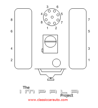
The A.I.M. (assembly instruction manual) is great for stuff like this. Yes, it has a diagram. Easy to see all the engine compartment wires. Dizzy rotates clockwise as you look down on it. Driver's side, front to back, 1-3-5-7. Passenger's side, front to back, 2-4-6-8. Now follow with the 1 8 4 3 6 5 7 2 sequence.
Without you filling out your profile, it's a little harder for us to help with information. Are you using other-than-stock spark plugs? Several manufacturers of wires (e.g. Jacobs, Delco, etc.). What kind of driving style? There's a lot of folks here with tons of experience.
Without you filling out your profile, it's a little harder for us to help with information. Are you using other-than-stock spark plugs? Several manufacturers of wires (e.g. Jacobs, Delco, etc.). What kind of driving style? There's a lot of folks here with tons of experience.

 01-11-2008, 10:02 AM
#6
Drifting

I used this exact diagram and found all my wires needed to be clocked back one spot counterclockwise on the distributor. I couldnt get it to run. My friend who is a mechanic on the pier in Long Beach saw it immediately. Maybe its my setup as the firing order is the same but #1started at the # 2 spot and so on. If it works for you dont let me confuse you, but if you run into a problem you may want to look at this as an option.
01-11-2008, 10:52 AM
#8
Drifting
I used this exact diagram and found all my wires needed to be clocked back one spot counterclockwise on the distributor. I couldnt get it to run. My friend who is a mechanic on the pier in Long Beach saw it immediately. Maybe its my setup as the firing order is the same but #1started at the # 2 spot and so on. If it works for you dont let me confuse you, but if you run into a problem you may want to look at this as an option.
Steve
PS: Plugs are plugs, wires are wires, save money.
01-11-2008, 11:45 AM
#9
Administrator
Member Since: Jul 2000
Location: About 1100 miles from where I call home. Blue lives matter.
Posts: 51,365
Received 5,321 Likes
on
2,770 Posts
 01-11-2008, 12:50 PM
#10
Drifting
I used this exact diagram and found all my wires needed to be clocked back one spot counterclockwise on the distributor. I couldnt get it to run. My friend who is a mechanic on the pier in Long Beach saw it immediately. Maybe its my setup as the firing order is the same but #1started at the # 2 spot and so on. If it works for you dont let me confuse you, but if you run into a problem you may want to look at this as an option.
 at myself, don't know why I didn't spot that. That's not my diagram, just one I found on another website to help out the OP. You are correct, that doesn't match the stock configuration. Sorry for the confustion. :o
 This one is correct, just not as "clear":
 01-11-2008, 03:38 PM
#11
Racer

Actually, the position of #1 on the distributor to the pass. side stems back to 1955, if you check the maintenance manual that's where it's put. The later way suits the HEI style better.
BTW did you know that you can now get HEI caps which are phased correct for cylinder position and firing order.
BTW did you know that you can now get HEI caps which are phased correct for cylinder position and firing order.
01-11-2008, 05:19 PM
#12
Drifting
The first drawing is more clear to me, but it really doesn't matter...put #1 wherever it falls on the cap, and then follow it around according to the firing order.
You can drop the distributor in anywhere, and still end up with proper wire routing, usually the vac advance can is the limiting factor.
Steve
You can drop the distributor in anywhere, and still end up with proper wire routing, usually the vac advance can is the limiting factor.
Steve
01-11-2008, 06:15 PM
#13
Pro
Member Since: Jan 2007
Posts: 589
Likes: 0
Received 0 Likes
on
0 Posts
 01-11-2008, 11:38 PM
#16
Racer

427basketcase
I was thinking the same thing...OEM SBC is: 1 8 4 3 6 5 7 2 (as mentioned).
If someone installed a 4/7 cam conversion it would be: 1-8-7-3-6-5-4-2
I did grin...but it is something to be aware of when trouble shooting.
(They say switching the firing order of 4 and 7 is worth 5 to 30 HP?, but you need the 4/7 cam installed)
Last edited by 33Chevy; 01-11-2008 at 11:44 PM.
01-12-2008, 10:57 AM
#17
Melting Slicks


Good picture!!
You can remember the installation without a picture.
Note; looking down on the top of the distributor cap, how the distributor wire connection for number 1 cylinder is the closest connection and in-line with number 1 cylinder. This is the best position for the cap to allow for distributor timing (most uninterrupted cap movement at this position).
Firing order is written on the intake manifold, (raised numbers manufactured on the intake)
 01-12-2008, 12:00 PM
#18
Racer
Is it the same for the BB 454
I used this exact diagram and found all my wires needed to be clocked back one spot counterclockwise on the distributor. I couldnt get it to run. My friend who is a mechanic on the pier in Long Beach saw it immediately. Maybe its my setup as the firing order is the same but #1started at the # 2 spot and so on. If it works for you dont let me confuse you, but if you run into a problem you may want to look at this as an option.
01-12-2008, 12:19 PM
#19
Safety Car


 01-13-2008, 08:16 AM
#20
Pro
Member Since: Dec 2006
Location: wilmington nc
Posts: 665
Likes: 0
Received 0 Likes
on
0 Posts