
C4 Frame and suspension CAD files
 01-05-2008, 08:42 PM
#1
Team Owner

Thread Starter
Member Since: Mar 2001
Location: Boston, Dallas, Detroit, SoCal, back to Boston MA
Posts: 30,594
Received 238 Likes
on
166 Posts

Frame and suspension CAD files
Doesn't anyone have, or know where I can get CAD files for the C4 Corvette's frame and suspension?
I found lot of the C4's frame dimensions in the FSM
I really want to input the whole suspension into a computer.
I'm going to coil overs and this would really help pick out the rate.
Also I'm thinking of making some modifications.
C4's are camber challenged, but just laying the upper a-arms against the frame doesn't do it. I've tried that, and it compromises braking too much.
If anyone has there car apart in the garage, can he measure the easy stuff?
A-arms dogbones etc.
I can then start work on the CAD file.
I'll provide the CAD file to anyone who helps me out.
BTW I really hope the upper a-arms in the front aren't pointing DOWN while at rest. That would explain a lot!
 01-05-2008, 09:29 PM
#2
Racer

Member Since: May 2005
Location: Lodi NJ
Posts: 255
Likes: 0
Received 0 Likes
on
0 Posts

Hi Brian,
Yes, a stock c4 when at rest the upper arms are pointed slightly down (negative camber loss under initial compression ) also if you look at the cross shaft on the upper "A" arm it is on an upward angle higer in the front then the rear. Anti dive
When the suspension is initially compressed you loose camber until you compress it enough to get past the center line, parallel to the ground,(which may never happen in stock trim) only then can you get negative camber gain. Interesting geometry!!!
Just rambling
Have fun
Yes, a stock c4 when at rest the upper arms are pointed slightly down (negative camber loss under initial compression
) also if you look at the cross shaft on the upper "A" arm it is on an upward angle higer in the front then the rear. Anti dive When the suspension is initially compressed you loose camber until you compress it enough to get past the center line, parallel to the ground,(which may never happen in stock trim) only then can you get negative camber gain. Interesting geometry!!!
Just rambling
Have fun
01-05-2008, 10:30 PM
#4
Le Mans Master


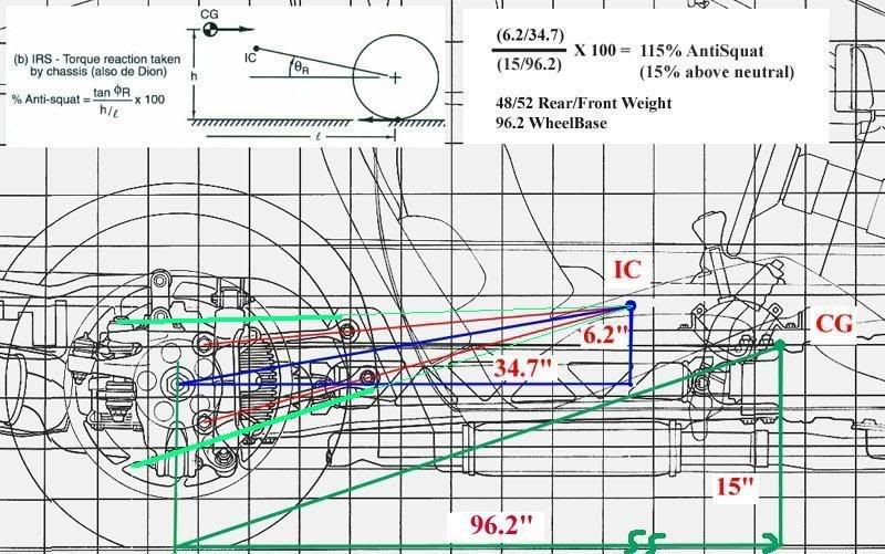
11/05 SuperL98 created a thread about Anti-Squat that generated
some informative comments. Perhaps some pieces to your puzzle might
be found within. There were images (and measurements IIRC).
These no longer display, but perhaps the OP would resurrect them upon
request?
Anti Squat on a C4 - Why so much?
I have some front lower control arms I could pull out for measurements
if this would help and if the data isn't already available elsewhere.
Mike Antoniak's book, Cor-Vette Specs (ISBN-10: 0933534515) is
very thorough. If you don't have it, I will see what might be available
there.
.
01-06-2008, 01:30 PM
#5
Team Owner
Thread Starter
Member Since: Mar 2001
Location: Boston, Dallas, Detroit, SoCal, back to Boston MA
Posts: 30,594
Received 238 Likes
on
166 Posts
Thanks, I PM'ed the people in that thread, since it's closed.
The end goal is to put the geometry into a suspension analyzer.
Something like this:
http://www.mitchellsoftware.com/prod01.htm


I have SolidWorks, and that may handle what I need to do.
What I need measured is geometries that are critical to how it moves.
ie) center to center distances, but not thicknesses.
If it would help I can make drawings showing what I need.
Items like the dogbone bushing center-to-center lengths should be easy to measure.
On the a-arms for instance, I need the center of the bushing hole to the center of where the ball joint pivot moves, which will be hard to measure. I need to know where the rollbar is connected, where the spring hits, where the shock is connected. These will tell me what spring rates to get.
This is no small task, but when it's done, I'm hoping to come up with some simple solutions to some of the handling issues we have.
The end goal is to put the geometry into a suspension analyzer.
Something like this:
http://www.mitchellsoftware.com/prod01.htm
I have SolidWorks, and that may handle what I need to do.
What I need measured is geometries that are critical to how it moves.
ie) center to center distances, but not thicknesses.
If it would help I can make drawings showing what I need.
Items like the dogbone bushing center-to-center lengths should be easy to measure.
On the a-arms for instance, I need the center of the bushing hole to the center of where the ball joint pivot moves, which will be hard to measure. I need to know where the rollbar is connected, where the spring hits, where the shock is connected. These will tell me what spring rates to get.
This is no small task, but when it's done, I'm hoping to come up with some simple solutions to some of the handling issues we have.
Last edited by BrianCunningham; 01-06-2008 at 01:37 PM.
01-06-2008, 02:19 PM
#6
Le Mans Master
Sample info from Cor-Vette Specs for a 1987 model.
This gives an idea of which portions of the quest can be satisfied
by obtaining a copy of Mr. Antoniak's book.
This gives an idea of which portions of the quest can be satisfied
by obtaining a copy of Mr. Antoniak's book.
WIDTH & LENGTH
Tread (front): 59.6"
Tread (rear): 60.4"
Wheelbase: 96.2"
FRONT:
Travel full jounce: 3.6"
Travel full rebound: 3.7"
Spring size: 45.7" x 3.9" x 0.52" (base); 45.7" x 3.9" x 0.56" (Z51)
Spring rate: 296 lb/in (base); 380 lb/in (Z51)
Spring rate at wheel: 92.6 lb/in (base); 110.9 lb/in (Z51)
REAR:
Travel full jounce: 3.6"
Travel full rebound: 2.8"
Spring size: 48.7" x 2.24" x 0.87" (base); 48.7" x 2.24" x 0.98" (Z51)
Spring rate: 233 lb/in (base); 330 lb/in (Z51)
Spring rate at wheel: 130.2 lb/in (base); 173.6 lb/in (Z51)
ECT:
Wheel offset: 1.26"
Axis inclination at camber: 8.744�
Front wheel at curb mass, service caster: 6.0�, +/- 0.5�
Front wheel at curb mass, service camber: 0.8�, +/- 0.8�
Front wheel at curb mass, service toe-in: 0.0�, +/- 0.1�
Rear wheel at curb mass, service camber: 0.0�, +/- 0.5�
Rear wheel at curb mass, service toe-in: 0.0�, +/- 0.1�
.
Tread (front): 59.6"
Tread (rear): 60.4"
Wheelbase: 96.2"
FRONT:
Travel full jounce: 3.6"
Travel full rebound: 3.7"
Spring size: 45.7" x 3.9" x 0.52" (base); 45.7" x 3.9" x 0.56" (Z51)
Spring rate: 296 lb/in (base); 380 lb/in (Z51)
Spring rate at wheel: 92.6 lb/in (base); 110.9 lb/in (Z51)
REAR:
Travel full jounce: 3.6"
Travel full rebound: 2.8"
Spring size: 48.7" x 2.24" x 0.87" (base); 48.7" x 2.24" x 0.98" (Z51)
Spring rate: 233 lb/in (base); 330 lb/in (Z51)
Spring rate at wheel: 130.2 lb/in (base); 173.6 lb/in (Z51)
ECT:
Wheel offset: 1.26"
Axis inclination at camber: 8.744�
Front wheel at curb mass, service caster: 6.0�, +/- 0.5�
Front wheel at curb mass, service camber: 0.8�, +/- 0.8�
Front wheel at curb mass, service toe-in: 0.0�, +/- 0.1�
Rear wheel at curb mass, service camber: 0.0�, +/- 0.5�
Rear wheel at curb mass, service toe-in: 0.0�, +/- 0.1�
Last edited by Slalom4me; 01-06-2008 at 02:33 PM.
01-06-2008, 02:46 PM
#7
Drifting

Man that was a long time ago 
The images still seam to be on my CF homepage, but they don't link anymore?
Haven't logged in for awhile...
logged in and now they seam to have come back up
I did lay the rear out in solidworks and had started on a design with an adjustable control arm bracket, but lets just say I lost the files during an "unplanned" carear change
Haven't had time to do much with that since.
P.S. I did my measuring with machinist rulers crawling around on the gagrage floor, just to get the general layout. I wouldn't be machining parts based on them ... without verification ...
01-06-2008, 02:59 PM
#8
Team Owner
Thread Starter
Member Since: Mar 2001
Location: Boston, Dallas, Detroit, SoCal, back to Boston MA
Posts: 30,594
Received 238 Likes
on
166 Posts
This picture is a BIG help.


Combine it with this one

And a lot of the rear suspension behavior can be done.
Do you have these as well?
All I have for plans are these pictures.
http://temp.corvetteforum.net/c4/iris//sideview.jpg
http://temp.corvetteforum.net/c4/iris//dimen.jpg
http://temp.corvetteforum.net/c4/iris//1e.jpg
http://temp.corvetteforum.net/c4/iris//1d.jpg
http://temp.corvetteforum.net/c4/iris//1c.jpg
http://temp.corvetteforum.net/c4/iris//1b.jpg
http://temp.corvetteforum.net/c4/iris//1a.jpg
http://temp.corvetteforum.net/c4/iris//1.jpg
Thanks
Combine it with this one
And a lot of the rear suspension behavior can be done.
Do you have these as well?
All I have for plans are these pictures.
http://temp.corvetteforum.net/c4/iris//sideview.jpg
http://temp.corvetteforum.net/c4/iris//dimen.jpg
http://temp.corvetteforum.net/c4/iris//1e.jpg
http://temp.corvetteforum.net/c4/iris//1d.jpg
http://temp.corvetteforum.net/c4/iris//1c.jpg
http://temp.corvetteforum.net/c4/iris//1b.jpg
http://temp.corvetteforum.net/c4/iris//1a.jpg
http://temp.corvetteforum.net/c4/iris//1.jpg
Thanks
01-06-2008, 03:18 PM
#9
Tech Contributor
Member Since: Jun 2004
Location: I tend to be leery of any guy who doesn't own a chainsaw or a handgun.
Posts: 18,342
Received 766 Likes
on
548 Posts

Brian,
I was looking for similar info about a year ago while building the C4 suspension mounts on my '69 frame. I ended up doing what looks good to me, measurement-wise, and making most of the pickup points adjustable or replaceable (I put the front A-arm mounts inside the A-arms, allowing me to put about 10* of negative camber in if I wanted to do something that silly.) I can also change the anti-dive and roll center numbers without a lot of the secondary effects that happen when the mounts are fixed in only one spot or plane. I didn't know precisely what a big block car with a C4 suspension would want for geometry specs, so I made them adjustable or replaceable.
Keep us updated on your info search.
01-06-2008, 03:35 PM
#10
Drifting
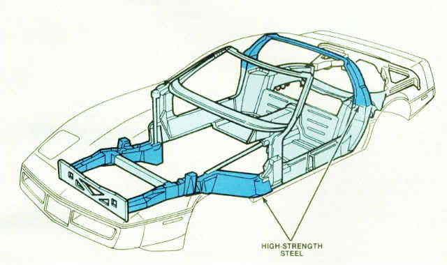
I figured you would have these, but if not....
The original "marketing" CAD drawings of the 1984.
These show in corvette picturebooks, as overhead slides the marketing guy's would show.
How accurate to scale from? Don't know........
http://temp.corvetteforum.net/c4/iri...ette_side1.gif
http://temp.corvetteforum.net/c4/iri...tte_frame2.gif
http://temp.corvetteforum.net/c4/iri...tte_frame1.gif
http://temp.corvetteforum.net/c4/iri...ette_frame.gif
BTW ... I am almost sure I ran across a 3D C4 model someone had done for SusProg3D ... back then. Long time ago, but I'll see if I still have a line on it.
Last edited by SuperL98; 01-06-2008 at 03:44 PM.
01-06-2008, 06:46 PM
#12
Race Director

Interesting thread! What changes do you think can be made?
01-06-2008, 11:40 PM
#13
Team Owner
Thread Starter
Member Since: Mar 2001
Location: Boston, Dallas, Detroit, SoCal, back to Boston MA
Posts: 30,594
Received 238 Likes
on
166 Posts
I want to get the compete stock geometry down before modifying it.
That way I can measure the stock ones and see how good my model is.
69427,
WOW, I thought you bought one of the conversion frames that are available.
Aardwolf,
The 1st thing I want to do is fix that front geometry.
The top a-arm should point up, not down at rest. So either the balljoint needs to go up or the frame side needs to go down, or both.
The second thing I want to fix is that rear geometry. The dogbones are way too short!
I don't know how many here realize it, but GM actually ripped off Dick Guldstrand's rear suspension design for the C3 when they built the C4. The trouble is the bean counters got a hold of it and messed it up in the process! Take a look at the dogbones, they run all the way to the back of the upright, thus making them at least twice as long. Also instead of a toelink, he has two beafy locating members spaced equally apart and on the same plane.

I might acually just buy his upright and adapt them to the C4.
Not only would I get the better geometry, but I'd get the beefier drivetrain, and cheaper bearings.
BTW does anyone have the front pic to go with this one?
I used to have it but now I can't find it
That way I can measure the stock ones and see how good my model is.
69427,
WOW, I thought you bought one of the conversion frames that are available.
Aardwolf,
The 1st thing I want to do is fix that front geometry.
The top a-arm should point up, not down at rest. So either the balljoint needs to go up or the frame side needs to go down, or both.
The second thing I want to fix is that rear geometry. The dogbones are way too short!
I don't know how many here realize it, but GM actually ripped off Dick Guldstrand's rear suspension design for the C3 when they built the C4. The trouble is the bean counters got a hold of it and messed it up in the process! Take a look at the dogbones, they run all the way to the back of the upright, thus making them at least twice as long. Also instead of a toelink, he has two beafy locating members spaced equally apart and on the same plane.
I might acually just buy his upright and adapt them to the C4.
Not only would I get the better geometry, but I'd get the beefier drivetrain, and cheaper bearings.
BTW does anyone have the front pic to go with this one?
I used to have it but now I can't find it
01-07-2008, 07:56 AM
#14
Racer
Member Since: May 2005
Location: Lodi NJ
Posts: 255
Likes: 0
Received 0 Likes
on
0 Posts
I want to get the compete stock geometry down before modifying it.
That way I can measure the stock ones and see how good my model is.
69427,
WOW, I thought you bought one of the conversion frames that are available.
Aardwolf,
The 1st thing I want to do is fix that front geometry.
The top a-arm should point up, not down at rest. So either the balljoint needs to go up or the frame side needs to go down, or both.
The second thing I want to fix is that rear geometry. The dogbones are way too short!
I don't know how many here realize it, but GM actually ripped off Dick Guldstrand's rear suspension design for the C3 when they built the C4. The trouble is the bean counters got a hold of it and messed it up in the process! Take a look at the dogbones, they run all the way to the back of the upright, thus making them at least twice as long. Also instead of a toelink, he has two beafy locating members spaced equally apart and on the same plane.
I might acually just buy his upright and adapt them to the C4.
Not only would I get the better geometry, but I'd get the beefier drivetrain, and cheaper bearings.
BTW does anyone have the front pic to go with this one?
I used to have it but now I can't find it
Thanks
Frank
01-07-2008, 12:17 PM
#15
Team Owner
Thread Starter
Member Since: Mar 2001
Location: Boston, Dallas, Detroit, SoCal, back to Boston MA
Posts: 30,594
Received 238 Likes
on
166 Posts
Done right I can keep the rear caster the same.
What I'm really after is less fore & aft movement of the tire as it moves up and down. Right now as the inside tire compress it move back quite a bit, and the outside tire moves forward.
Here's a rough idea, of course when I'm done with the front I'll need to change the roll axis.
What I'm really after is less fore & aft movement of the tire as it moves up and down. Right now as the inside tire compress it move back quite a bit, and the outside tire moves forward.
Here's a rough idea, of course when I'm done with the front I'll need to change the roll axis.
01-08-2008, 07:34 PM
#16
Le Mans Master
Brian,
I have C3 (rear) and C5 (front and rear) modeled in Catia V5 but no C4.
Download and install the functional demo of Performance Trends Suspsension Analyzer. I know for sure that it comes with all of the C5 points and it may also have C4.
I have C3 (rear) and C5 (front and rear) modeled in Catia V5 but no C4.
Download and install the functional demo of Performance Trends Suspsension Analyzer. I know for sure that it comes with all of the C5 points and it may also have C4.
01-09-2008, 01:27 AM
#19
Team Owner
Thread Starter
Member Since: Mar 2001
Location: Boston, Dallas, Detroit, SoCal, back to Boston MA
Posts: 30,594
Received 238 Likes
on
166 Posts
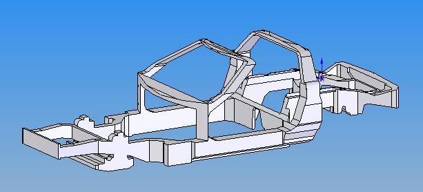
1st crack at the C4's frame.
This doen't need to be the that accurate, so long as the suspension pick-up points are. It's more for reference.
GM's
Mine
Thanks, I'll drop them an email.
This doen't need to be the that accurate, so long as the suspension pick-up points are. It's more for reference.
GM's
Mine
Brian,
I have C3 (rear) and C5 (front and rear) modeled in Catia V5 but no C4.
Download and install the functional demo of Performance Trends Suspsension Analyzer. I know for sure that it comes with all of the C5 points and it may also have C4.
I have C3 (rear) and C5 (front and rear) modeled in Catia V5 but no C4.
Download and install the functional demo of Performance Trends Suspsension Analyzer. I know for sure that it comes with all of the C5 points and it may also have C4.
Thanks, I'll drop them an email.
Last edited by BrianCunningham; 01-09-2008 at 01:30 AM.
01-09-2008, 11:14 PM
#20

Hi Brian,
Yes, a stock c4 when at rest the upper arms are pointed slightly down (negative camber loss under initial compression ) also if you look at the cross shaft on the upper "A" arm it is on an upward angle higer in the front then the rear. Anti dive
When the suspension is initially compressed you loose camber until you compress it enough to get past the center line, parallel to the ground,(which may never happen in stock trim) only then can you get negative camber gain. Interesting geometry!!!
Just rambling
Have fun
Yes, a stock c4 when at rest the upper arms are pointed slightly down (negative camber loss under initial compression
) also if you look at the cross shaft on the upper "A" arm it is on an upward angle higer in the front then the rear. Anti dive When the suspension is initially compressed you loose camber until you compress it enough to get past the center line, parallel to the ground,(which may never happen in stock trim) only then can you get negative camber gain. Interesting geometry!!!
Just rambling
Have fun


